
3 Circumference & Bisecting Angles
CIRCUMFERENCE AND HOW TO FIND
There are a few ways to find the circumference of pipe and round tube. Knowing the circumference is key into building accurate templates for use with pipe. The more accurate your numbers are when developing these template, the better fit you will have. As with anything, practice and experience in building templates will also increase accuracy.
The most used method for figuring circumference is using the formula of Pi x diameter. 6” OD round tube has a circumference of 18.85”. 6”x Pi=18.85”. When it comes to working with pipe, you need to be aware that pipe is measure nominally. This means that 6” pipe is not 6” OD. Luckily, all pipe manufactures follow a standard and there is a countless number of tables and charts that list all pipe sizes and even include the circumference of all sizes! Please refer to index to locate these tables, charts and other information.
Over the next several sections we will begin to develop templates for use with pipe. No matter the complexity of the template there are several key concepts that are used with all of them, including determining the circumference. We will only introduce these concepts in detail once, if you need help please refer back to an earlier sections.
We will be talking about dividing the circumference of pipe into several equal parts that will help develop the template. We will refer to these lines as element lines. The more element lines you have the more accurate the fit.
Like was stated earlier, there are many ways that craftspeople have figured out solutions to complex problems, this is book offers one of those.
Below we have some 4” pipe. By referring to the chart we can see that the OD of that pipe is 4.50”. Also on the chart we see that it has a total circumference of 14.125”. For this book, we will divide all circumferences into 16 equal spaces in which will become the element lines. The handy chart in the back also shows us the spacing for dividing circumference into 16 parts, as well as 12, 8, 6, 4 and 2. Remember, the more element lines you have the more accurate your template will be. If we did not have the chart, you would have to divide the total circumference by the number of spaces needed. Some rounding will be required when doing this but you need to be aware that being off 1/16”, 16 times will end up being off by a full 1”.
If you divide 14.125 by 16 you end up at .883. The chart in the back state .875. .875, or 7/8” is much easier to work with on a tape measure than .883. The difference is about 1/132 per line, this will be acceptable.
To get started we will draw a side view that will show the height of our section of pipe. Next we need to draw in our stretch-out. We know the circumference is 14.125. We can draw a vertical adjacent to side view a pipe and then extend out the horizontal lines (shown in red) that are the top and bottom lines from side view to establish the overall height of the pipe and run them out to a length of 14.125”. Once we have the height and stretch-out complete we are ready to place the element lines.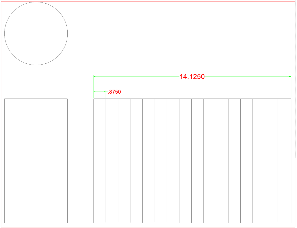
When working with pipe and developing templates you will need to brush up on some basic geometry and the bisecting of angles. We will use a compass for this task.
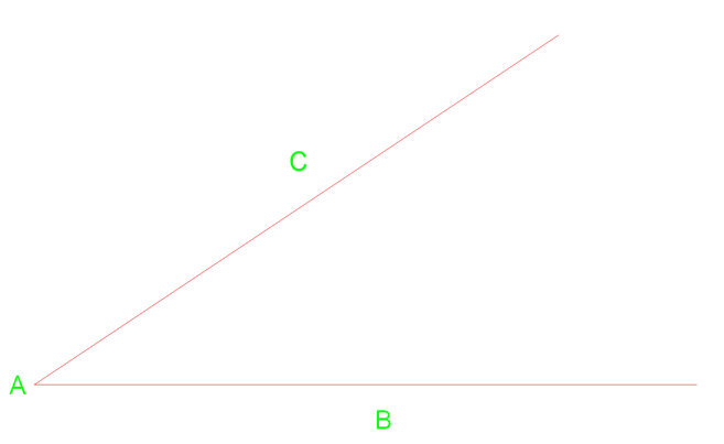
Below we have angle CAB with a vertex of point A.
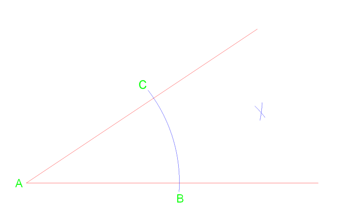
First we can draw an arc from vertex A that crosses the line near point C & B. From those two intersection we can then draw two additional arcs to the right.
From vertex A draw a line that crosses at point D where the arc intersect.
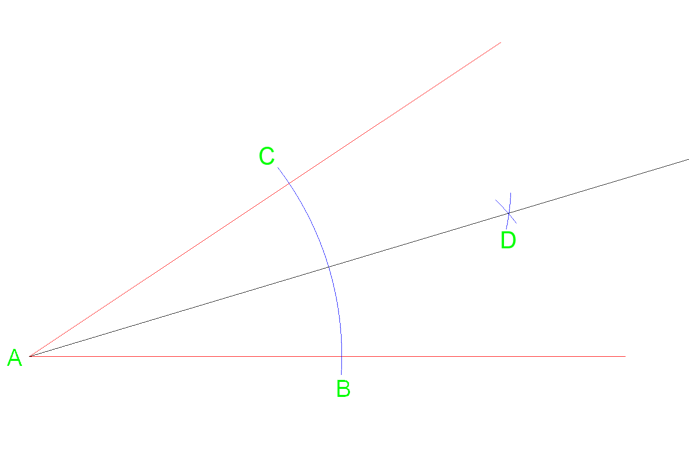
Using this method will equally split the angle into two angle of the same measurement. This method and can repeated if necessary to split it again into 4 equal parts.
Lets try a similar method on a circle. The drawn circle has a diameter of 3” so a radius of 1 ½”.
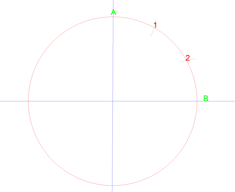
By setting your compass to the radius of the circle, 1 ½” and then drawing an arc from point A and then B they intersect at 1 & 2. If you then to draw a line from the center of the circle to each point, you just divided that quarter of the circle into three equal parts. See below…
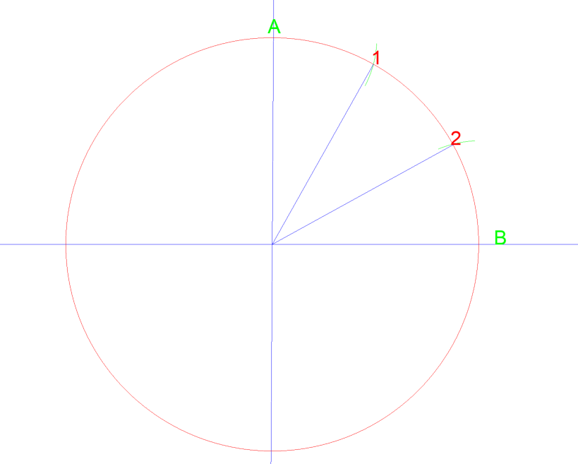
If you then did this again between A, 1, 2, & B you can divide that quarter of a circle into 6 equal areas.
As we covered briefly earlier, we use numbers to help with lining up of where lines will connect. These lines will be used when we are joining two or more parts together to make one assembly. As we keep going, you will better understand how this numbering system works.
