
Lesson 6
15 Testing Motor Components
Ken Dickson-Self
Testing capacitors
Warning: A good capacitor stores an electrical charge and may remain energized after power is removed. Before touching it or taking a measurement:
- Turn all power OFF
- Use your multimeter to confirm that power is OFF
- Carefully discharge the capacitor by connecting a resistor across the leads. Be sure to wear appropriate personal protective equipment.
To safely discharge a capacitor: After power is removed, connect a 20,000 Ω, 2-5 watt resistor across the capacitor terminals for 20 – 40 seconds. (You can use your multimeter set to volts to confirm the capacitor is fully discharged.)
- Visually inspect the capacitor. If leaks, cracks, bulges or other signs of deterioration are evident, replace the capacitor.
- Turn the dial to the Capacitance Measurement mode (
 ).
). - For a correct measurement, the capacitor will need to be removed from the circuit and properly discharged.
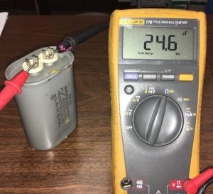
- Connect the test leads to the capacitor terminals. Keep test leads connected for a few seconds to allow the multimeter to automatically select the proper range.
- Read the measurement displayed. Value should fall within specified range (or +/- 10% of stated value). DMM will display OL if a) the capacitance value is higher than the measurement range or b) the capacitor is faulty.
Troubleshooting single-phase motors is one of the most practical uses of a digital multimeter’s Capacitance Function.
A capacitor-start, single-phase motor that fails to start is a symptom of a faulty capacitor. Such motors will continue to run once operating, making troubleshooting tricky. Failure of the hard-start capacitor for HVAC compressors is a good example of this problem. The compressor motor may start, but soon overheat resulting in a breaker trip.
Three-phase power factor correction capacitors are typically fuse protected. Should one or more of these capacitors fail, system inefficiencies will result, utility bills will most likely increase and inadvertent equipment trips of may occur. Should a capacitor fuse blow, the suspected faulty capacitor farad value must be measured and verified it falls within the range marked on the capacitor.
Motor Nameplates
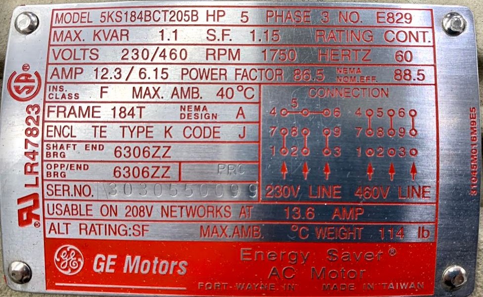
There are many different types of electric motors, and they all have unique parameters, requirements and specifications. Motor nameplates contain information concerning motor performance and mounting parameters, defined by the National Electrical Manufacturers Association (NEMA). These parameters include:
- Manufacturer’s type and frame designation – This can include information such as the frame mounting pattern, shaft diameter and shaft height
- Horsepower – Measure of motor’s mechanical output. This is based on the motor’s full-load torque and speed. Horsepower = Motor Speed x Torque / 5250. If your application’s requirement falls between two horsepower ratings, generally pick the larger-sized motor.
- RPM – Sometimes called “slip speed” (as opposed to synchronous speed). Determined by winding pattern and power frequency.
- Locked-rotor Code Letter – Uses letters A to V to define the locked rotor kVA per HP. Typically, A is the lowest. B is greater than A. C is greater than B, etc. A higher code may require replacing other equipment, such as motor starters to handle greater current.
- Maximum ambient temperature and time rating or duty cycle- Standard motors are rated for continuous duty (24/7) at their rated load and maximum ambient temperature. Specialized motors can be designed for “short-time” requirements where intermittent duty is all that’s needed. These motors can carry a short-time rating from 5 minutes to 60 minutes.
- Voltage – 230V motor running at 208V will be less efficient, but a 480V motor works at 460V because voltage drop is assumed (if motors are designed to handle a 10% voltage difference, then a 480V motor should be able to handle any voltage from 432-528V.
- Frequency – Input frequency (60 Hz in the US, 50 Hz in many other countries)
- Phase – The number of AC power lines supplying the motor
- Current draw – When motor is fully loaded. Unbalanced phases and under voltage can cause current deviation.
- Power factor – Ratio of the active power to the apparent power (at full load).
- Efficiency – Power calculation = (Output / Input) x 100
- Service factor – This will only by on the nameplate if it is higher than one. Service factor (SF) is an indication of how much overload a motor can withstand when operating normally within the correct voltage tolerances. For example, the standard SF for open drip-proof (ODP) motors is 1.15. This means that a 10-hp motor with a 1.15 SF could provide 11.5 hp when required for short-term use. n general, it’s not a good practice to size motors to operate continuously above rated load in the service factor area.
- Wiring diagrams
- Bearing – Drive-end (sometimes called shaft-end) and non-drive-end bearing identification.
