
Lesson 6
16 Homework 6
hansonj
- Complete the table below
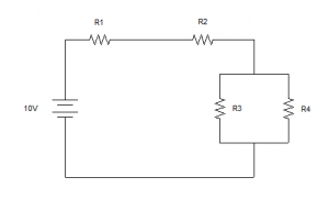
| R1 | R2 | R3 | R4 | R3//R4 | Total | |
| E | 10V | |||||
| I | ||||||
| R | 200Ω | 300Ω | 400Ω | 400Ω |
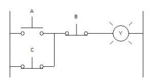
- Create a truth table based upon the ladder diagram below:
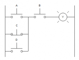
- Create a truth table based upon the ladder diagram below
- Draw a ladder diagram of a 2-wire circuit using a temperature switch.
- Draw a ladder diagram of a 3-wire circuit using 2 E-Stops
- I thought that I wired up the circuit shown below. As soon as I plugged the circuit in, the motor starter coil immediately energized and pulled-in. When I push either STOP button, the coil will de-energize. Give at least two things that could be wrong.
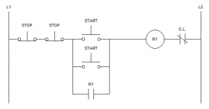
- I wired up another motor starter, identical to the circuit shown in problem #6. I am 100% sure that all of the wiring is correct. When I plug my circuit in, nothing happens (which is how it should be, right?), but when I press either START button, the coil will not energize. What could be causing this problem? Give at least two things that could be wrong.
- Using the same circuit that’s shown in problem #6, what voltage should I measure across the coil when it is energized? (Zero, Ghost, or Source)
- Using the same circuit that’s shown in problem #6, what voltage should I measure across any of the START pushbuttons when the coil is energized? (Zero, Ghost, or Source)
- How can using a 2-wire circuit be dangerous?
