
Lesson 2
8 Homework 2
Ken Dickson-Self
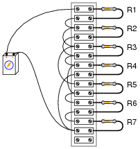
- Calculate the resistance between points A and B for the following resistor networks:

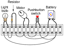
- From this circuit (with components attached to a “terminal strip”), draw an appropriate schematic diagram. Then explain the function of the resistor and what happens when the pushbutton is pressed (assuming it is normally open).
- Complete the table of values for this circuit:

- Draw a schematic for the following:
- Considering your two inputs (A and B) in the image below, what type of logic is used to actuate the coil of CR3? Lamp 1? Lamp 2? If Lamp 2 never turns on, what components of the circuit could be causing the problem?

- Create a truth table for the following diagram:
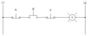 What conditions must exist in order for the light to energize?
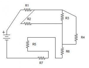
 - Create a simplified schematic for the following complex circuit:
- Complete the table for the following schematic:
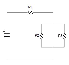 Express all current in milliamps.
R1 R2 R3 R2 // R3 Total E 48 V I R 120 Ω 120 Ω 200 Ω - Create a truth table for the following diagram:
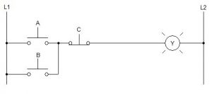 What conditions must exist in order for the light to energize?
This chapter is an adaptation of Lessons in Electric Circuits by Tony R. Kuphaldt (on allaboutcircuits.com), and is used under a Design Science License.
Media Attributions
- Logic Problem
- Complex Circuit
- Combination Circuit
- Logic Problem 2
