Lesson 1
2 Electrical Fundamentals
Ken Dickson-Self
Hopefully by the time you’re considering wiring up motors and their controls, you already have a knowledge of electricity and how it behaves. The following is just a brief refresher, but any technician considering the wiring of three-phase motors should have a solid understanding of electrical fundamentals. If you do not have this understanding, please use your favorite education resource to complete training.
Electrons moving around in a never-ended loop is considered a circuit. Circuits that are closed allow for electron flow. Circuits that are open (broken) do not allow for electron flow.
Electricity has three main components. Voltage is the amount of potential electrical energy between two points, and it is usually represented by the letter E (for electromotive force) and is measured in volts, abbreviated with V. Current is the flow of electrons from negatively-charge atoms toward atoms with a positive charge. We measure current in Amperes or Amps (abbreviated A), and the symbol for current is I. Current that travels in only one direction we call direct current (DC). Current that changes direction at regular intervals we call alternating current (AC). The final component is resistance. Resistance (abbreviated R) is the opposition to current flow, and it is measured in ohms (abbreviated with the Greek letter Omega, Ω).
These three terms are related to one another in the following way: E = I * R. Knowing this, if we ever know any two of these variables in a circuit, we can always calculate the third. Two other ways to express the same equation are: I = E / R and R = E / I.
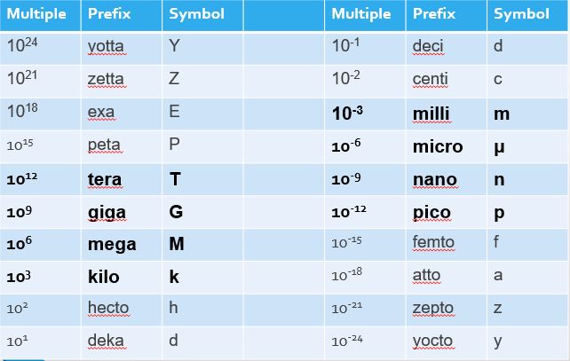
In electricity, we often use scientific notation and prefixes with the units we measure. If you’re unfamiliar with these concepts, you may want to study them a bit more. With electricity, some multiples and prefixes are used more often than others. These are in bold in the table below.

When building electrical circuits, components can be connected in two basic ways: either in series with one another or in parallel.
Series
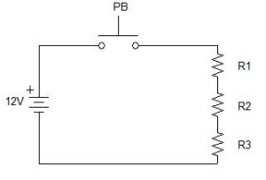
When there is only one path for current flow, the components are said to be in series. Look at this example of a series circuit.

The circuit has three resistors (labeled R1, R2, and R3), and these resistors are in series with each other. Notice too that the push button (labeled PB) is also in series with the resistors, as is the 9-volt battery. There is only one path for electrons to take, and all electrons must follow the same path through the circuit when the push button is pushed.
Because the electrons only have one path, the current flow is the same throughout the entire circuit, and all resistances are cumulative. Let’s say that R1 has a resistance of 10Ω, R2 has a resistance of 20Ω, and R3 has a resistance of 30Ω. Because all resistances are cumulative and current is the same through, voltage at any particular component is determined by that component’s resistance. The formula look like this:
Series
RTotal = R1 + R2 + R3 + …
ITotal = I1 = I2 = I3 = …
ETotal = ER1 + ER2 + ER3 + …
In our example, total resistance is 60 ohms (10Ω + 20Ω + 30Ω). Since the total resistance is 60Ω in a 12-volt system, the total current must be 0.2A, or 200mA (12V/60Ω). Now that total current is known, voltage at each load can be calculated. For instance, the voltage at R1 (E=IR) is going to be 0.2A * 10Ω, or 2V. Voltage at R2 is 4V and voltage at R3 is 6V. Notice that all of our voltages (2V, 4V, 6V) add up to the source voltage of 12V. This rule applies to all series circuits.
Parallel
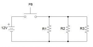
In parallel circuits, current flow has more than one path. This changes the behavior of the electrons in the circuit. First, the voltage across parallel components is no longer split among them. Since they are in parallel with one another (electrically common), they each get full voltage. Notice on the diagram below where the black connecting dots are located. Each of those represent two (or more) locations where voltage is going to be available equally in either direction.

So, in this example, when the push button is pushed, 12 volts becomes available to every resistor in the circuit, since they are each parallel with each other (the push button, however, is still in series with all resistors). So, if every resistor has the full source voltage available, how much current will be flowing through the circuit? This depends on the resistance of each “branch” or “rung” of our circuit. We simply calculate the current through each resistor, then add them together to get the total current (see below).
Parallel
ETotal = ER1 = ER2 = ER3 = …
ITotal = I1 + I2 + I3 + …
RTotal = 1 / (1/R1 + 1/R2 + 1/R3 + …]
Total resistance, however, is now a little more difficult, because as resistors are added in parallel to our circuit, we’re providing more paths for electrons to flow. Each new path that’s added decreases the total resistance of the whole circuit. In fact, the total resistance of our parallel circuit MUST be lower than the resistance of the lowest resistor.
Let’s use the same resistance values as the series circuit (R1 has a resistance of 10Ω, R2 is 20Ω, and R3 is 30Ω). Knowing that our total resistance is now going to be less than 10Ω, let’s do the math.
RTotal = 1 / (1/10 + 1/20 + 1/30)
RTotal = 1 / (0.1 + 0.05 + 0.0333)
RTotal = 1 / 0.1833
RTotal = 5.45Ω
Clever technicians always look for ways to verify results. In this case, we could calculate current for our circuit at each resistor.
IR1 = 12/10 IR2 = 12/20 IR3 = 12/30
IR1 = 1.2A IR2 = 0.6A IR3 = 0.4A
ITotal = 1.2A + 0.6A + 0.4A = 2.2A of total current
Using Ohm’s Law, our total resistance should be equal to total voltage divided by total current, and indeed, if we divide 12V by 2.2A, we get a total resistance of 5.45Ω. matching our previous result. Nice.
Testing Components
Switches/Contacts
Switches and contacts are designed to allow and stop the flow of current. When a switch or set of contacts are closed, the resistance should be very low (near zero), meaning that very little voltage is dropped (near zero). When a switch or set of contacts are open, the resistance should be infinite (OL on many meters), meaning that all potential voltage is available across those open contacts (assuming there aren’t other opens in series with the one being measured).
Protection Devices
Testing fuses, circuit breakers, or overloads is similar to testing switches, except they are designed to always allow current flow. It’s only when a protection device has experienced current higher than its specified amount that the device opens the circuit, stopping current. When testing resistance, these devices should have very low resistance. Since they are placed in series with the circuit they are designed to protect, we don’t want them using up available voltage. A protection device with infinite resistance is “blown” or in its “tripped” state. When measuring voltage across one of these devices, when good there should be very little voltage dropped. If source voltage is present, the device is “blown” or in its “tripped” state.
Loads
Loads are designed to use applied voltage to do the work of the circuit. This could be running a motor, lighting a bulb, or actuating a relay. Loads need to have some amount of resistance (this amount will vary by load and can be found by checking the manufacturer’s specifications or measuring similar “known good” parts). Loads that measure either no resistance or an infinite amount of resistance are not good. Because loads are designed to use the available voltage, measuring voltage at a load may not always tell you if the load is good or bad. If the load has an internal open, source voltage will be read at the load. If the load is working properly, source voltage will also be found at the load. If the load is shorted, most likely, any protection devices in the circuit (fuses, circuit breakers, overloads) will be tripped, due to the increased current.
Relays
Because relays operate like an electrically-controlled switch, you have two components to test. First is the coil of the relay, which acts as a load. Next are the contacts within the relay, which act as switches. The contacts of the relay are often in a different circuit than the coil, but all of these components are tested as described above.
Transformers
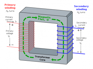
Lastly are transformers. Transformers are typically used to change AC voltage by either stepping it up or stepping it down. Transformers consist of two coils of wire wrapped around an iron core. The coils of wire behave like a typical load and can be tested similarly, as described above.

- Test primary coil
- Test secondary coil
- Measure Resistance (Rs) from primary to secondary coil (should be no continuity)
- Measure Rs from Primary coil to transformer housing (should be no continuity)
- Measure Rs from Secondary coil to transformer housing (should be no continuity)
Ladder Diagrams
Media Attributions
- Transformer © BillC is licensed under a CC BY-SA (Attribution ShareAlike) license

