
2.4 Check Valves
Describe the basic purposes of valves in fluid power systems.
Define the terms: body, ports/ways, spool, poppet, seal, springs, actuation/adjustment methods
Describe the different valve mounting methods: inline, subplate, manifold, cartridge, stack
Draw the schematic symbol and cutaway view of a basic poppet style check valve. Identify direction of free flow. Identify direction of blocked flow.
Describe how a primitive pressure relief valve can be created with a check valve.
Define cracking and full open pressure.
Discuss the main disadvantage of a basic poppet style check valve in the free flow direction and how a right angle check valve overcomes this disadvantage. Draw a cutaway view of a right angle check valve.
Draw the schematic symbol and cutaway view of a restriction (orifice) style check valve. Identify direction of free flow. Identify direction of restricted flow. Describe how a restriction (orifice) style check valve works.
Draw the schematic symbol and cutaway view of a pilot to open check valve. Describe how a pilot to open check valve works in the absence and presence of pilot pressure.
Draw the schematic symbol and cutaway view of a pilot to close check valve. Describe how a pilot to close check valve works in the absence and presence of pilot pressure.
Describe how check valves are employed in the following applications: foot valves, manual pumps, filters in bidirectional systems, quick disconnects, valve bypasses, clogged filter bypasses
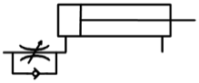
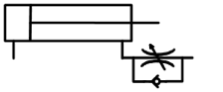
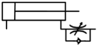
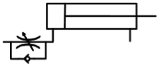
Determine how these 4 flow control valves with check valve bypasses influence speed of extension or retraction.
 |
 |
 |
 |
