
14 Chapter 5: Surface Grinder
OBJECTIVE
After completing this unit, you should be able to:
• Identify Surface Grinder.
• Identify Procedures.
• Describe Dressing the Wheel procedures.
• Describe the Ring Test.
• Describe replacing the Grinding Wheel.
• Describe procedure select the grinding wheel.
• List principal abrasives with their general areas of best use.
• List principal bond with the types of application where they are most used.
• Identify by type number and name , from unmarked sketches, or from actual wheels.
• Interpret wheel shape and size markings together with five basic symbols of a wheel specification into description of the grinding wheel.
• Given several standard , common grinding jobs, recommend the appropriate abrasive, approximate grit size, grade, and bond.
The Surface Grinder is mainly used in the finishing process. It is a very precise tool which uses a stationary, abrasive, rotating wheel to shave or finish a metallic surface which is held in place by a vise. This vise, which is part of a table, or carriage is moved back and forth under the abrasive wheel. The surface grinder can cut steel in pieces no bigger than 18” long by 6” high by 8” wide. The table of the grinder is also magnetic, which aids in holding the material still. These magnets can be toggled by means of a lever located on the front side of the grinder. This instrument has a maximum cut of .005 of an inch, and a minimum cut of .005 of an inch. The movement of the grinder can be an automatic, back and forth motion, or manually moved as required.
Safety Precautions
Besides regular machine shop safety rules, these are some tips on how to use this machine safely:
• Always wear safety glasses as this machine may send shavings in all directions.
• Always wait for the wheel to reach maximum speed before using it, as there may be
• If you have long hair, you should keep it tied back, so that it does not get caught in the machine.
• Never strike the wheel against the material as this could cause faults in the wheel, which may result in a loss of integrity and it may fly apart.
• Always make sure that the guard is in place over the grinding wheel, as this protects the user from the shavings that are removed from the material.
• Always make sure the material is securely fastened in place.
• Always make sure the magnetic table is clean before placing material on it, as shavings may scratch your material or even cause the material to slide wheel you are using the grinder.
• Ensure that the grinder has a start/stop button within easy reach of the operator.
• Check the grinding wheel before mounting it. Make sure it is properly maintained and in good working order.
• Follow the manufacturer’s instructions for mounting grinding wheels.
• Keep face of the wheel evenly dressed.
• Ensure that the wheel guard covers at least one half of the grinding wheel.
• File off any burrs on the surface of work that is placed on the magnetic chuck.
• Clean the magnetic chuck with a cloth and then wipe with the palm of your hand.
• Place a piece of paper slightly larger than workpiece in the center of chuck.
• Position work on the paper and turn on the power to the magnetic chuck.
• Check that the magnetic chuck has been turned on by trying to remove work from the chuck.
• Check that the wheel clears the work before starting the grinder.
• Run a new grinding wheel for about one minute before engaging the wheel into the work.
• Wait for the wheel to reach maximum speed before using it as there may be unseen faults in the wheel.
• Stand to one side of the wheel before starting the grinder.
• Turn off coolant before stopping the wheel to avoid creating an out-of-balance condition.
• Keep the working surface clear of scraps, tools and materials.
• Keep the floor around the grinder clean and free of oil and grease.
• Use an appropriate ventilation exhaust system to reduce inhalation of dusts, debris, and coolant mists. Exhaust systems must be designed and maintained appropriately.
• Follow lockout procedures when performing maintenance work.
Procedure for Use
• The first step in using the surface grinder, is to make sure that the material you wish to shape can be used in the grinder. Soft materials such as aluminum or brass will clop up the abrasive wheel and stop it from performing effectively, and it will then have to be cleaned. This process is explained in the Maintenance section. The maximum size of a material that the grinder can machine is 18” long by 8” wide by 6” high.
• The next step is to make sure the material is secured. This is done by use of a vice, and then by engaging the magnetic clamp. Once the material is secure, it must be manually positioned under the abrasive wheel. This is done by turning the longitude and latitude wheels located on the front of the grinder. The abrasive wheel itself can be moved slightly to get the material in the perfect position.
• Then the machine may be started. It should reach maximum speed before you try to use it for the safety reasons. If the wheel is working properly, manually used when very precise work needs to be done.
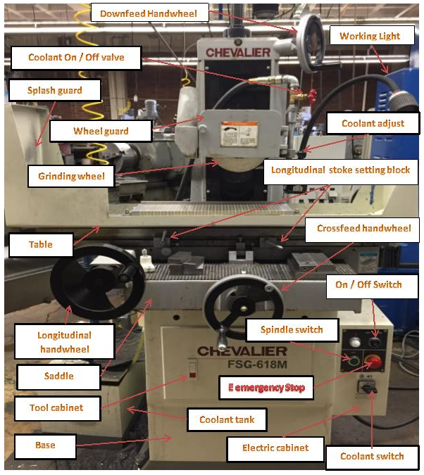
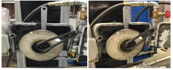
Figure 1. Chevalier Surface Grinder
Dressing the Wheel
1. Place the diamond wheel dresser onto the bed.
2. Keep the diamond dresser ¼ of an inch to the left of the center of the wheel.
3. Lock the dresser onto the bed by turning the magnetic chuck on.
4. Turn on the machine power by turning the switch to the “ON” position. Then press the green button to start the spindle.
5. Move the grinding wheel down using the vertical table handwheel until it barely makes contact with the dresser.
6. Turn the machine off after making contact with the dresser.
7. Turn the machine on again. While the wheel is spinning, lower the grinding wheel down in the Z direction until it makes a small plume of dust.
8. Once the small plume of dust has been made, make one pass back and forward along the Y-axis. Stop the machine when the dresser has made on pass back and forward.
9. When stopping the machine, make sure that the dresser is about ½ inches away from the wheel.
10. Check the wheel to see if it is clean. If not, repeat steps 8 and 9.
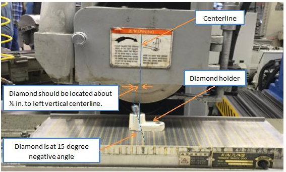
Figure 2. Dressing the wheel
Ring Test
Grinding wheels must be inspected and “ring-tested” before they are mounted to ensure that they are free from cracks or other defects. Wheels should be tapped gently with a light, nonmetallic instrument. A stable and undamaged wheel will give a clear metallic tone or “ring.”
Performing the ring test:
Make sure the wheel is dry and free of sawdust or other material that could deaden the sound of the ring.
You will need a hard plastic or hard wood object, such as the handle of a screwdriver or other tool, to conduct the test. Use a wood mallet for heavier tools. Do not use metal objects.
- Suspend the wheel on a pin or a shaft that fits through the hole so that it will be easy to turn, but do not mouth the wheel on the grinder. If the wheel is too large to suspend, stand it on a clean, hard surface.
- Imagine a vertical plumb line up the center of the wheel.
- Tap the wheel about 45 degrees on each side of the vertical line, about one or two inches from the wheel’s edge. (Large wheels may tapped on the edge rather than the side of the wheel.)
- Turn the wheel 180 degrees so that the bottom of the wheel is now on top.
- Tap the wheel about 45 degrees on each side of the vertical line again.
- The wheel passes the test if it gives a clear metallic tone when tapped at all four points. If the wheel sounds dead at any of the four points, it is cracked. Do not use it.
Replacing the Grinding Wheel
- Open the wheel case. If the wheel case is very tight, this may require a pair of brace wrench, wrench and a rubber mallet.
- Remove the metal plate on top by loosening the screws that are holding it to the wheel case.
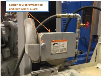
Figure 3. Remove metal plate and wheel case
3. Behind the wheel, on the spindle, there is a hole. Insert the brace wrench on the right side into the back of the spindle. The brace wrench should be able to fit into the hole.
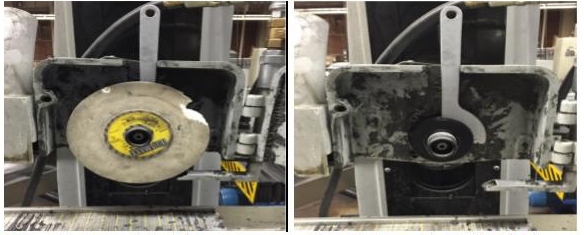
Figure 4. Brace wrench into hole Figure 5. Remove the grinding wheel
Grinding Procedure
- Ensure the proper wheel for the stock is being used. There are different grinding wheels for aluminum, stainless steel, and titanium.
- Clean the bed before placing the workpiece onto it. This will prevent interference with the magnetic chuck.
- Place magnetic parallels around the workpiece to ensure the workpiece does not shift during grinding.
- Turn the magnetic chuck on to secure the pieces onto the bed.
- Adjust the bed and saddle position to center the stock below the wheel.
- Lower the wheel an inch above the workpiece.
- Take a piece of paper and place it between the wheel and the stock. Move the paper back and forth while simultaneously lowering the wheel until the paper is no longer able to move to zero the z-axis. See figure 1.
- Zero the z-axis of the workpiece by setting the dial on downfeed handwheel to 0 inches. See figure 2.
- Lock the table Longitudinal stoke setting block so that there is about an inch of overtravel at each end of the table stroke.
- Adjust the table position so the wheel sits about an inch to the right of the workpiece.
- Lower the wheel to the desired depth of grinding. There should be a maximum downfeed of 0.001 inch per pass.
- Ensure the wheel is not in contact with the workpiece before turning the main power on. Press the green button to turn the spindle on and turn the coolant switch on.
- Grind the stock by making passes left to right along the x-axis.
- Once the first strip of the workpiece has been sufficiently ground, turn the y-axis handwheel half a turn clockwise.
- Grind another strip of the workpiece from left to right along the x-axis.
- Repeat until the workpiece is fully ground, then repeat all of the previous steps for the other side.
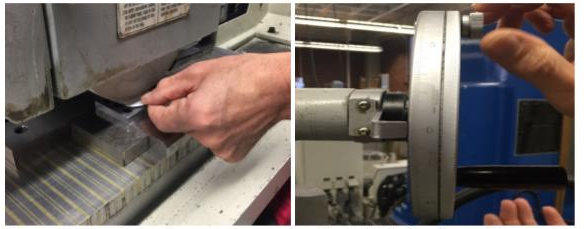
Figure 6. Setting the z axis Figure 7. Setting downfeed
Grinding Wheel
Select the grinding wheel:
Keep in mind that a grinding wheel is a form of cutting tool, and except in the case of wheel for general purpose grinding, the abrasive, grit size, grade and structure, bond type should be selected to fit the particular job on which the wheel is to be used, just as a cutter, drill or tap is selected for its specific job.
To select the grinding wheel, there are eight factors which affect the choice of the grinding wheel specifications. There are:
1. Grinding wheel manufactures instruction.
2. Material to be ground and its hardness.
3. Amount of stock to be removed and finish required.
4. Are of grinding contact.
5. Severity of the grinding operation.
6. Wheel speed.
7. Feed rate
8. Operating technique.
Suggestions:
1. First consider the material to be ground and its hardness. These effect the choice of abrasive, grift size, and grade or hardness of the wheel.
- Aluminum oxide are best for steels, while Silicon carbide abrasives are better suited to grinding cast iron, nonferrous metals and nonmetallic materials.
- A relatively fine grit size works best on taking heavier cuts can be used advantageously on soft and ductile materials that are readily penetrated.
- The hardness of the material to be ground also affects choice of the wheel grade or hardness. A harder grade can be used on soft, easily penetrated materials than on hard materials which naturally tend to dull the wheel faster. The softer grades release the dull grains more readily to present new, sharp grains to the work.
2. Second factor, in selecting a wheel in the amount of stock to be removed and the finish required. These affect the choice of grift size and bond as follows:
- A relatively coarse grit size is selected for rapid stock removal without regard for finish as rough grinding; a fine grift should be used where a high finish is desired.
- Vitrified bonded wheels are generally used where a commercial finish satisfactory. The organic bonds, resinoid, rubber and shellac, produce the highest finish.
3. The area of grinding contact between the wheel and the work affects the choice of grift size and grade.
- A coarse grift is required when the contact area is relatively large, as in surface grinding with cup wheels, cylinders or segments, to provide adequate chip clearance between the abrasive grains. As area of contact becomes smaller and the unite pressure tending to break down the wheel face becomes greater, finer grit wheels should be used.
- As to the grade or hardness, on large area of contact a soft grade will provide normal breakdown of the wheel, insuring continuous, free-cutting action. A harder grade, on the other hand, is needed to stand up under the increasingly higher unit pressure as the area of contact becomes smaller.
4. The severity of the grinding operation affects the choice of abrasive and grade.
- A tough abrasive like 4A Aluminum Oxide should be used for rough, heavy duty grinding of steel.
- The milder abrasives like 32 and 38 Aluminum Oxide are best for lighter precision grinding operations on steels and semisteels, while the intermediate 57 and 19 Aluminum Oxide abrasives are used for precision and semiprecision grinding of both mild and hard steels.
- The severity of the grinding operation also influences the choice of grade. Hard grade provide durable wheels for rough grinding such as snagging, while medium and softer grade wheels can be used for precision type operations which are less severe on the wheel.
5. The speed at which the grinding wheel is to be operated often dictates the type of bond.
- Vitrified bonded wheels should not be used at speeds over 6,500 s.f.p.m. With few exceptions, when the speed exceeds this figure, resinoid, rubber or shellac bonded wheels should be used. Note, the safe operating speed shown on the tag, wheel or blotter must never be exceeded.
6. Feed rate
- The higher the feed rate, the greater the grinding pressure is. If the grinding speed of workpiece must be increased, the feed rate will be increased, then the wear of the wheel will be faster. Therefore a harder grinding wheel is required.
- A standard wheel marking system is used for the identifying five major factors in grinding wheel selection:
- Type of abrasive
- Grit size
- Grade or hardness
- Structure
- Bond
First Symbol: Type of Abrasive
A wheel marked A 60-J8V indicates the following:
A – Fused aluminum oxide
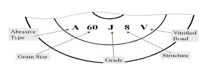
Figure 8: Grinding Wheel Marking
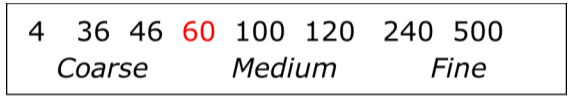
Second Symbol: Grit Size
The following scale can be used to determine grit:
Third Symbol: Grade of Hardness
- Hardness grade is a measure of bond strength of the grinding wheel.
- Bond material holds abrasive grains together in the wheel.
- The stronger the bond, the harder the wheel.
- Hardness grade is a measure of bond strength of the grinding wheel.
A to G are softer.
H to P are more medium grades.
R to Z are harder.
Fourth Symbol: Structure
- Structure, the spacing of the abrasive grains in the wheel is indicated by numbers.
1 is a dense structure.
8 is a more medium structure.
15 is an open structure.
Fifth Symbol: Bond
- Bond is identified by letter according to the following:
- V – Vitrified
- B – Resinoid
- R – Rubber
- E – Shellac
- M – Metal
Standard grinding wheel marking example:
1- A – 305 X 25 X 127 WA 46 K 8 V 7N 2000m/min
FROM(WHEEL TYPE): 1(Straight-plain)
FACE: A
SIZE: Dia. (D) X Width(W) X Bore(H)
ABRASIVE TYPE: WA (See Figure 2)
GRAIN SIZE: 46 (See Figure 2)
GRADE: K (See Figure 2)
STRUCTURE: 8 (See Figure 2)
BONE TYPE: V (See Figure 2)
MAKER CODE: 7N
MAX. RPM: 2000m/min.
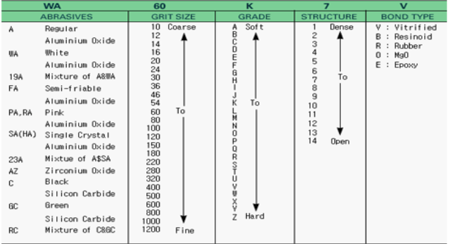
Figure 9: Grinding Wheel Selection Chart
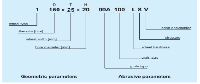
Figure 10: Grinding Wheel Selection Chart
UNITS TEST
1. Please list five Safety Precautions.
2. Please list five main parts of the surface grinders.
3. What is a diamond wheel dresser?
4. When Dressing the Wheel how far Diamond dresser should be located to the left of the center of the wheel?
5. What is a Ring Test?
6. How do you Performing the ring test?
7. When select the grinding wheel, there are eight factors which affect the choice of the grinding wheel specifications. Please list five out of eight factors.
8. Aluminum oxide grinding wheel are best for what?
9. A standard wheel marking system is used for the identifying factors in grinding wheel selection. Please all five major factors?
10. A wheel marked WA 80-L9B, Please indicates the following.
Chapter Attribution Information
This chapter was derived from the following sources.
Grinding and Buffing derived from Mechanical Engineering Tools by the Massachusetts Institute of Technology, CC:BY-NC-SA 4.0.
