
23 Unit 6: Haas Control
OBJECTIVE
After completing this unit, you should be able to:
- Identify the Haas Control.
- Identify the Keyboard.
- Describe Start/Home Machine procedure.
- Describe Door Override procedure.
- Describe Load Tools procedure.
- Describe Tool Length Offset (TLO) for each tool.
- Verify part zero offset(XY) using MDI.
- Describe the setting tool offset.
- Verify Tool Length offset using MDI.
- Describe the procedure of load CNC program.
- Describe the procedure of save CNC program.
- Explain how to run CNC program.
- Describe the use of cutter diameter compensation.
- Describe the shut down program.
Haas Control
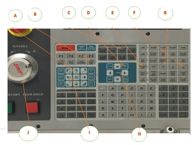
The Haas control is shown in Figures 18 and 19. Familiarize yourself with the location of buttons and controls. Detailed instructions on the following pages show how to operate the control.
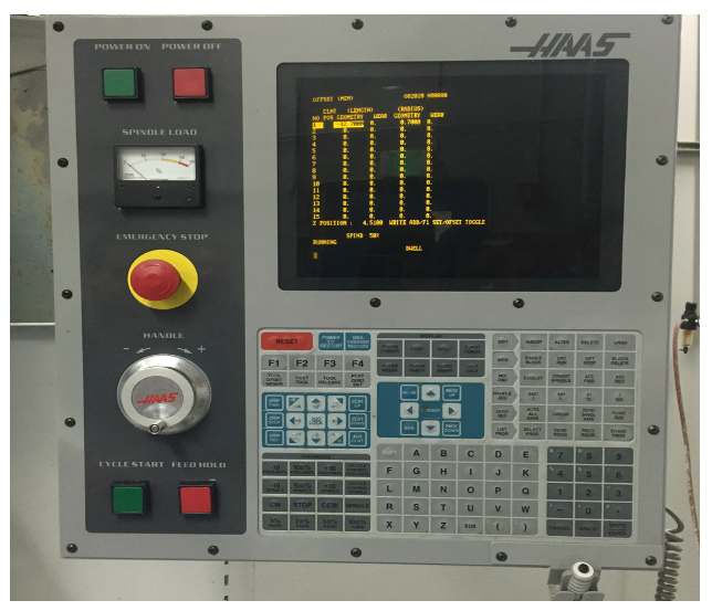
Figure 1. Haas CNC Mill Control Haas Keyboard
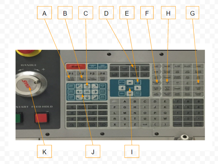
Keyboard
Keyboard keys are grouped into these functional areas:
1. Function Keys
2. Cursor Keys
3. Display Keys
4. Mode Keys
5. Numeric Keys
6. Alpha Keys
7. Jog Keys
8. Overrides Keys
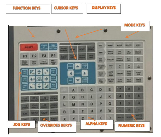
Figure 2. Haas CNC Control Buttons/ Keyboard keys
Start/Home Machine
Checklist:
1. Work Area: Made sure work area is Clear
2. Main Breaker: Turn On
3. Air Supply: Turn On Air to Correct pressure (at least 70PSI for tool changer to operate)
4. POWER ON: Press Green Button
5. Ensure Emergency Stop is not tripped. If it is, twist red knob right to release.
6. Wait until message 102 SERVOS OFF appears before proceeding.
7. RESET
8. Power On Restart
9. Ensure doors are closed and work area is clear.
10. Allow all machine axes to home before proceeding
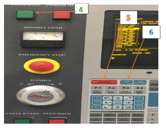
Figure 3. Start/Home Machine
Door Override
1. Mem: Select and Press Mem.
2. Setting Graph: Select and Press Setting Graph
3. Enter 51
4. Cursor: Press down arrow key and then the right arrow key to turn off
5. Write/Enter: Select and Press Write/Enter
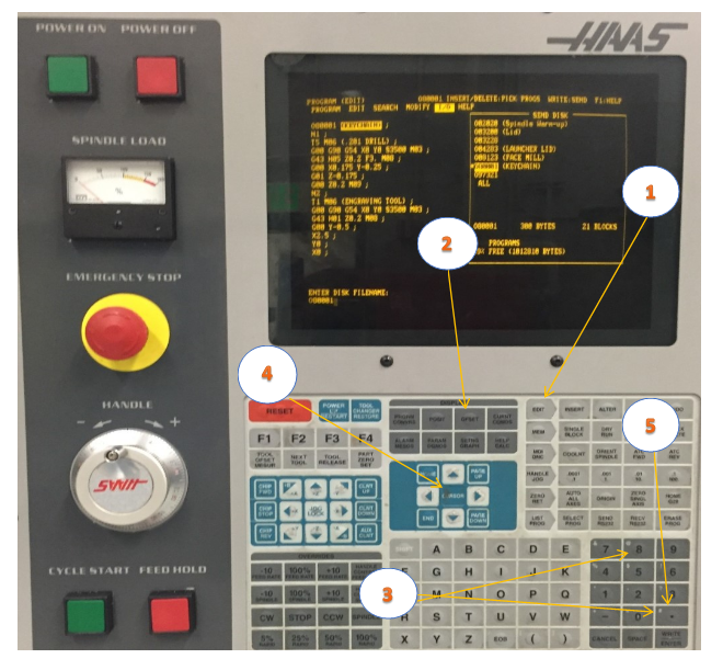
Figure 4. Door Override
Load Tools
Checklist:
1. MDI/DNC Key: Press the MDI/DNC button.
2. Tool Number:
- For example, to position the tool changer to T1,
- Press the T and then the 1 buttons.
3. ATC FWD: Press the ATC FWD button.
- Tool carousel will index to T1 position.
4. Position Tool in Spindle
- Do not grip by tool cutting flutes!
- Ensure tool taper is clean.
- Grip tool holder below V-flange to prevent pinching.
- Push tool into spindle.
- Ensure “dogs” on spindle line up with slots on tool holder.
5. Tool Release: Press the Tool Release button
- Machine will blow air thru spindle to clear debris.
- Gently push the tool upward and then release the Tool Release button.
- Ensure tool is securely gripped by spindle before releasing it.
6. Repeat steps 2-5 until all tools are loaded.
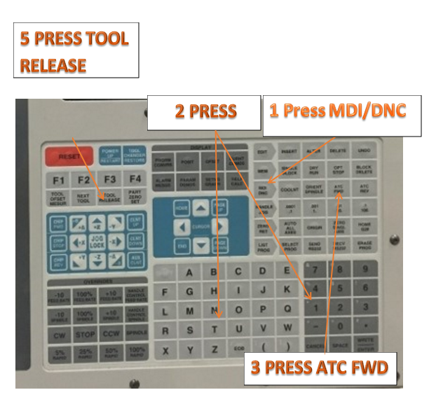
Figure 5. Load Tools
Setting Offsets
To machine a part accurately, the mill needs to know where the part is located on the table
and the distance from the tip of the tools to the top of the part (tool offset from home
position).
To manually enter offsets:
1. Choose one of the offsets pages.
2. Move the cursor to the desired column.
3. Type the offset value you want to use.
4. Press (ENTER) or (F1). The value is entered into the column.
5. Enter a positive or negative value and press (ENTER) to add the amount entered to the number in the selected column; press (F1) to replace the number in the column.
Jog Mode
Jog mode lets you jog the machine axes to a desired location. Before you can jog an axis,
the machine must establish its home position. The control does this at machine power-up.
To enter jog mode:
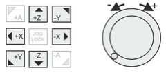
1. Press (HANDLE JOG).
2. Press the desired axis (+X, -X, +Y,-Y, +Z, -Z).
3. There are different increment speeds that can be used while in jog mode; they are (.0001), (.001), (.01) and (.1). Each click of the jog handle moves the axis the distance defined by the current jog rate. You can also use an optional Remote Jog Handle (RJH) to jog the axes.
4. Press and hold the handle jog buttons or use the jog handle control to move the axis.
Set Tool Length Offset (TLO)
Checklist:
1. Handle Jog Mode: Select the Handle Jog button.
- This sets machine to be controlled by the hand wheel.
2. Jog Increment: .01
- This sets the job increment so each click of the hand wheel moves the tool .01 inches in the jog direction.
3.Jog Direction: Press the Z button
- This sets the tool to move in Z when the jog handle is moved.
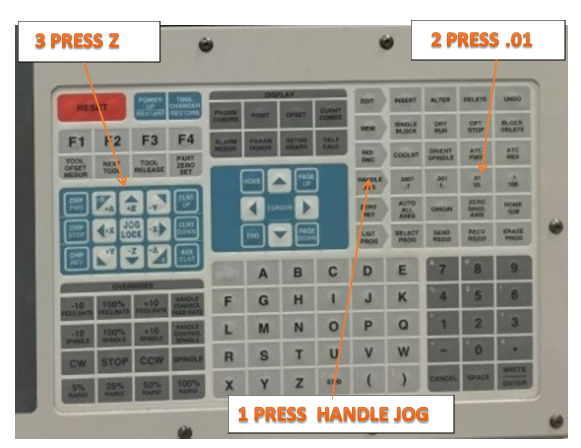
Figure 6. TLO
4. Offsets: Select and Press Offset
- Tool Offset page displays.
5. Cursor Arrows: Align for active tool
- Use the Up-Dn cursor keys (if needed) to move the highlighted bar on the graphics display over the offset values for the currently active tool.
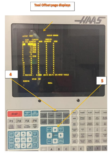
Figure 7. Offset
6.Use 1-2-3 Block to Set Tool Length
- Jog so tool is below top block.
- Apply slight pressure to block against tool. Use Jog Wheel to raise tool until the block just slides underneath it.
- Move block out of way and then move tool back down .01 inches below top of block.
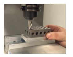
Figure 8
7. Jog Increment: .001
- Reduce jog increment and use jog handle to raise tool in .001 increments until it just slides under the block again.
8. Tool Offset Measure: Select and Press Tool Offset Measure
- This causes the control to enter the current position of the tool in the length offset register.
- Make sure the tool length number updates before proceeding.
9. Next Tool: Select and Press Next Tool
- This causes the current tool to be put away and the next tool to be loaded.
- Repeat steps 1 thru 9 until all tools are set.
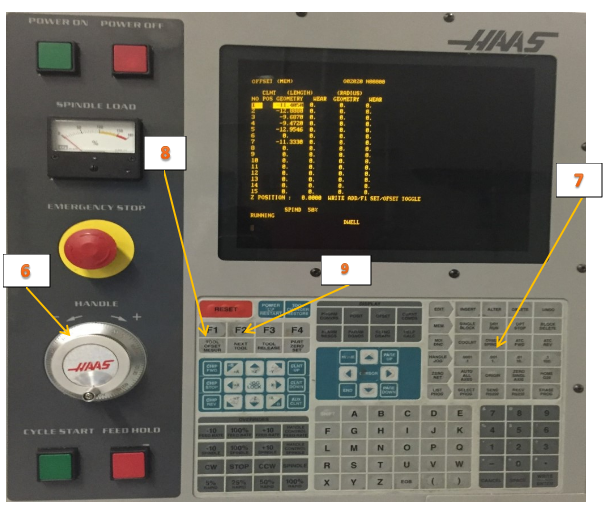
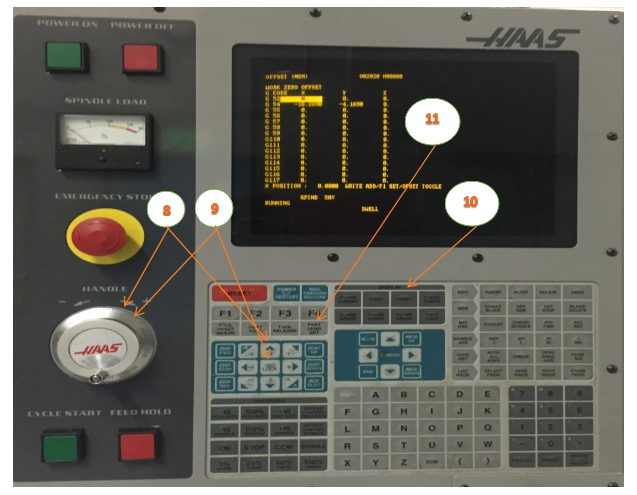
Figure 9. Offset Display Page
NOTE:
Setting tools requires manually jogging the machine with hands in the machine work envelope. Use extreme caution and observe the following rules:
• The spindle must be off.
• Never place your hand between the tool and the workpiece.
• Ensure the correct axis and jog increment are set before jogging.
• Move the handle slowly and deliberately. Keep your eyes on your hands and the tool position at all times.
• Never allow anyone else to operate the control when your hand is in the work area.
How to Access MDI
The Manual Data Input Mode (MDI) is one of the modes your CNC machine can operate in. The idea is to enter G-Codes or M-Codes on a line which are executed immediately by the machine–you don’t have to write an entire g-code program when a line or two will suffice. MDI offers a lot of power while requiring very little learning. You can even use MDI commands to machine your part. With MDI, CNC can be quick and dirty just like manual machining.
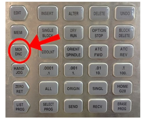
Figure 10. MDI
Press the MDI key on your CNC control panel to go to MDI mode.
For Example:
Press MDI/DNC
Erase Prog: Select and Press (to clear any commands)
Enter S1200 M03 (Spindle Speed 1200 RPM, On CW)
Setting Part Zero Offset Offset XY(Using Edge Finder)
Checklist:
1. MDI/DNC Key: Select and Press MDI/DNC
2. Erase Prog: Select and Press Erase Prog to clear any commands
3. Turn on Spindle Speed: S1200
- Press S1200 M03(Input): Select: Write/Enter
4. Cycle Start: Select
- Spindle will start CW at 1200 RPM
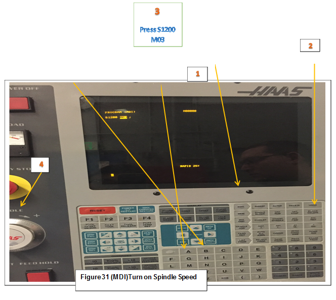
Figure 11. Turn on Spindle Speed (MDI)
5. Handle Jog: Select Handle Jog and Jog Increment: .01
6. Jog Handle: As Needed
- Select jog direction and use handle as required to place edge finder stylus alongside the left part edge.
7. Jog Increment: .001
- Move edge finder slowly until it just trips off center as shown below.
- This places the center of the spindle exactly .100 from the part edge
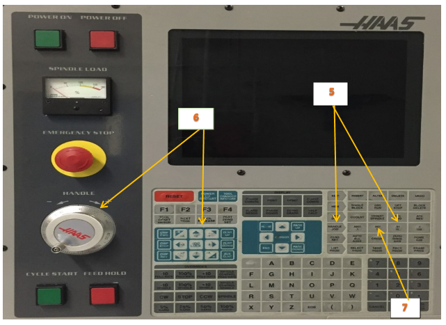
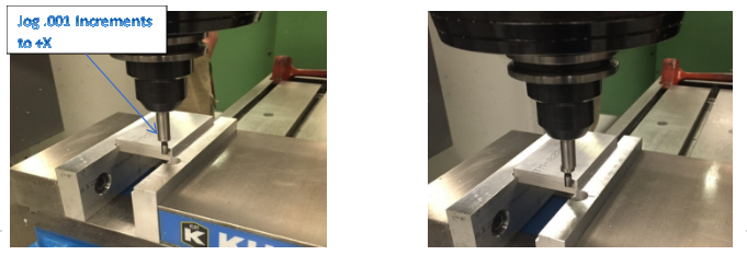
Figure 12. Just before tripping Figure 13. Just after tripping
8 .Jog Handle: Retract in Z 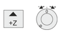
• Jog straight upward in Z until edge finder is above part and jog handle reads zero on the dial.
9. Jog Handle: Set jog direction to +X and rotate handle one full turn clockwise. 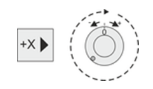
Since the control is in .001 increment mode, rotating the dial exactly one full turn places the center of the spindle directly over the left part edge.
10. Offset Page: Select and Press 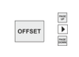
• Select Offset button and PgUp/PgDn buttons until Work Zero Offset page appears. Use Arrow keys to highlight G54 (or whatever fixture offset is to be set).
11. Part Zero Set: Press Part Zero Set
• This sets the G54 X value to the current spindle position.
12. Spindle Stop: Press spindle stop
13. For Setting the Y-axis repeat steps 6-11
Using MDI to verify Part zero offset
1. MDI/DNC Key: Select and Press MDI/DNC
2. Erase Prog: Select and Press (to clear any commands)
3. Enter G00 G90 G54 X0 Y0
4. Insert: Select and Press Insert
5. Cycle Start: Select and Press Cycle Start
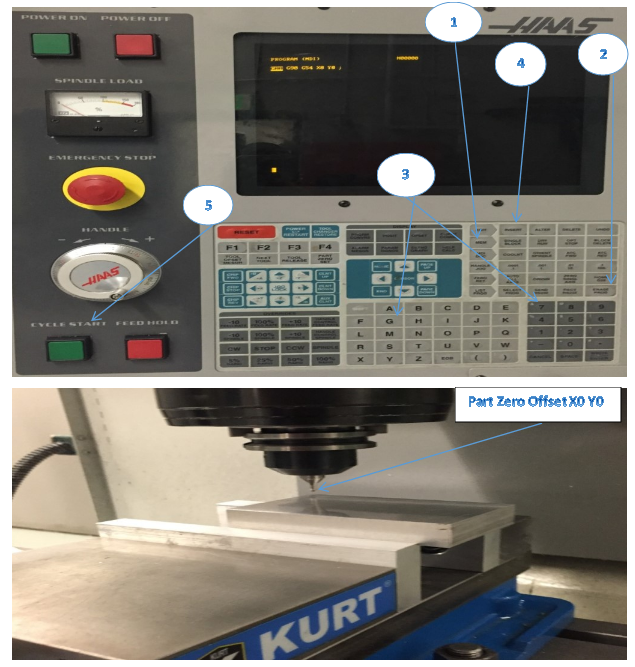
Part Zero Offset X0 Y0 (MDI)
- To shift the datum RIGHT in relation to the machine operator, ADD a shift amount to the offset X-value. For example, to shift X+.1, input .1 WRITE/ENTER.
- To shift the datum CLOSER to the machine operator, SUBTRACT a shift amount from the offset Y-value. For example, to shift Y-.1, input -.1 WRITE/ENTER
Setting Part Zero Offset XY(Using Mechanical pointer)
In order to machine a part, the mill needs to know where the part is located on
the table. You can use an edge finder, an electronic probe, or many other tools and
methods to establish part zero. To set the part zero offset with a mechanical pointer:
1. Place the material (1) in the vise and tighten.
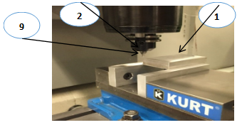
Figure 14. Setting Part Zero XY (Using Mechanical pointer)
2. Load a pointer tool (2) in the spindle.
3. Press (HANDLE JOG) (E).
4. Press (.1/100.) (F) (The mill will move at a fast
speed when the handle is turned).
5. Press (+Z) (A).
6. Handle jog (J) the Z-Axis approximately 1″ above the part.
7. Press (.001/1.) (G) (The mill will move at a slow speed when the handle is turned).
8. Handle jog (J)the Z-Axis approximately. 0.2″ above the part.
9. Select between the X and Y axes (I) and handle jog (J) the tool to the upper left corner
of the part (See Figure 36 above (9).
10. Press (OFFSET) (C) until the Active Work Offset pane is active.
11. Cursor (H) to G54 X-Axis column.
12. Press [PART ZERO SET] (B) to load the value into the X-Axis column. The second
press of [PART ZERO SET] (B) loads the value into the Y-Axis column.
Setting Tool Offset
The next step is to touch off the tools. This defines the distance from the tip of the tool to
the top of the part. Another name for this is Tool Length Offset, which is designated as H in
a line of machine code. The distance for each tool is entered into the Tool Offset Table.
Setting Tool Offset. With the Z Axis at its home position, Tool Length Offset is measured
from the tip of the tool (1) to the top of the part (2). See Figure 15.
1. Load the tool in the spindle (1).
2. Press (HANDLE JOG) (F).
3. Press (.1/100.)(G) (The mill moves at a fast rate when the handle is turned).
4. Select between the X and Y axes (J) and handle jog (K) the tool near the center of the part.
5. Press (+Z) (C).
6. Handle jog (K) the Z Axis approximately 1″ above the part.
7. Press (.0001/.1) (H) (The mill moves at a slow rate when the handle is turned).
8. Place a sheet of paper between the tool and the work piece. Carefully move the tool
down to the top of the part, as close as possible, and still be able to move the paper.
9. Press (OFFSET) (D).
10. Press (PAGE UP) (E) until you display the Program Tool Offsets window. Scroll to tool #1.
11. Cursor (I])to Geometry for position #1.
12. Press [TOOL OFFSET MEASURE] (A).
The next step causes the spindle to move rapidly in the Z Axis.
13. Press (NEXT TOOL) (B).
14. Repeat the offset process for each tool.

Figure 15. Setting Tool Offset (sheet of paper)
Using MDI to verify Tool Length offset
1. MDI/DNC Key: Select and Press MDI/DNC
2. Erase Prog: Select and Press (to clear any commands)
3. Enter G00 G90 G43 H01 Z2.00
4. Insert: Select and Press Insert
5. Cycle Start: Select and Press Cycle Start
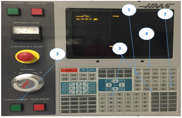
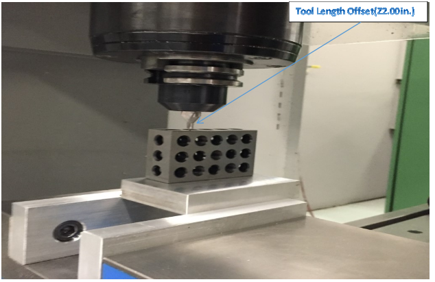
Figure 16. Tool length Offset (2.00 inch above part using 1 2 3 block to verify)
Load CNC Program
1. Edit: Select and Press Edit
2. F1: Select and Press F1
3. Cursor: Press the left arrow key to I/O and then the DN arrow key to move the highlight bar to Disk Directory.
4. Write/Enter: Select and Press Write/Enter
5. Cursor ( Disk Directory): Press the DN arrow key to program to load.
6. Write/Enter: Select and Press Write/Enter
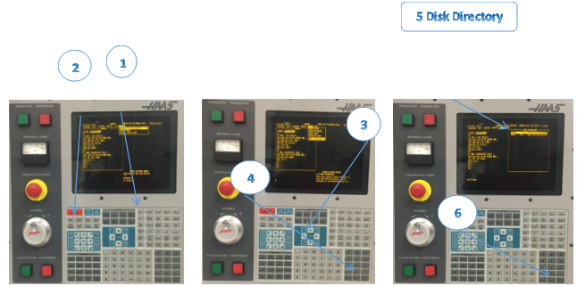
Figure 17. Load CNC Program
Save CNC Program
1. Edit: Select and Press Edit
2. F1: Select and Press F1
3. Cursor: Press the left arrow key to I/O and then the DN arrow key to move the highlight bar to Send Disk.
4. Write/Enter: Select and Press Write/Enter
5. Enter Disk File Name: O80001
6. Write/Enter
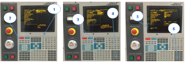 Figure 18. Save CNC Program
Run CNC Program
This is the preferred process for running a new program. Once a program is proven, all feed rates can be set to 100% and single block mode can be set to off.
Dry Run Operation
The machine executes all motions exactly as programmed. Do not use a work piece in the machine while dry run is operating. The Dry Run function is used to check a program quickly without actually cutting parts.
To select Dry Run:
1. While in MEM or MDI mode, press (DRY RUN).
When in Dry Run, all rapids and feeds are run at the speed selected with the jog speed buttons.
2. Dry Run can only be turned on or off when a program has finished or [RESET] is
pressed. Dry Run makes all of the commanded X Y Z moves and requested tool
changes. The override keys can be used to adjust the Spindle speeds.
Checklist:
1. Pre-Start
- Ensure vise or fixture is secure and that you have a safe setup.
- There should be no possibility that the work holding will fail to perform as required.
- Remove vise handles.
- Clear the work area of any tools or other objects.
- Close the machine doors.
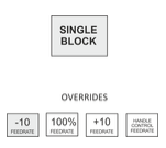
- Turn Single Block Mode On.
- Press Rapid Feedrate -10 button eight times to set rapid Feed Rate Override to 20% of maximum.
2. Start
- Place one hand on Feed Hold button and be ready to press it in case there are any problems.
- Press Cycle Start Button.
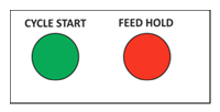
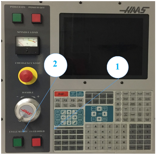
Figure 19. Run CNC Program
A common error is setting the Fixture or Tool Length offset incorrectly. When running a program for the first time, set the machine to Single block mode. Reduce rapid feed rate to 25%, and proceed with caution. Once the tool is cutting, turn off single block mode and let the program run. Do not leave the machine unattended, and keep one hand on the feed hold button. Listen, watch chip formation, and be ready to adjust cutting feed rates to suite cutting conditions.
Adjusting CDC Offsets
Machining operations that use Cutter Diameter Compensation (CDC: G41/G42) can be adjusted to account for tool wear and deflection. Measure across a finished feature on part and compare it with the desired value. Subtract the Actual from the Target sizes and enter the difference into the CDC register on the control for that tool. For example:
(Target Feature Size: 2.5000 ) – (Actual Feature Size: 2.5150) = Wear Value: -0.0150
The tool path will now be compensated for the size difference. Running the same operation again should result in the feature being exactly the target size
Wear compensation is used only on contour passes. It is not used for face milling, 3D milling, or drill cycles. Select the Wear Compensation option in your CAD/CAM software and, if needed, set a Tool Diameter Wear value as shown above. When used, the wear value is always a negative number. Always set Tool Diameter Geometry to zero for all tools since CAD/CAM software already accounts for the tool diameter by programming the tool center line path.
Checklist:
1. Offset Page: Select and Press Offset
2. Adjust Diameter Offset: Select and Enter Value
![]()
- Pg Up/Dn to highlight the tool to be adjusted.
- Enter a value using the numeric keypad.
- Example Tool Diameter Wear value as shown above: -0.0150
- Select and Press Writ/Enter
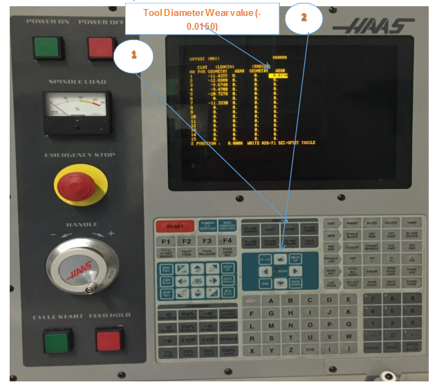
Figure 20. Adjusting CDC Offsets
Shut Down CNC Machine
Checklist:
1.Remove tool from spindle:
- Enter the number of an empty tool carousel.
- Select ATC FWD
2. Jog Machine to Safe Area:
• Select Jog
3.Shut Down Button: Press POWER OFF
Post Power-Down Checklist:
• Wipe spindle with a soft clean rag to remove coolant and prevent rusting.
• Put away tools.
• Clean up work area.
• Always leave the machine, tools, and equipment in the same or better condition than when you found them.
It is important to clean the machine after each use to prevent corrosion, promote a safe work environment, and as a professional courtesy to others. Allow at least 15-30 minutes at the end of each class for cleaning. At the very least, put away all unused tools and tooling, wash down the machine with coolant, remove standing coolant from the table, and run the chip conveyor.
UNIT TEST
1. Please lists eight functional areas of HAAS Keyboard.
2. Describe how to Door override.
3. Explain how to load Tools.
4. Describe MDI and give one example.
5. Explain how to set part zero offset.
6. Please describe using MDI to verify part zero offset.
7. Explain how to set Tool Length offset
8. Please describe using MDI to verify Tool Length offset.
9. Describe how to save CNC program.
10. Please Explain the shut down procedure.
