
20 Unit 3: Vertical Milling Center Machine Motion
OBJECTIVE
After completing this unit, you should be able to:
- Understand the Vertical Milling Center Machine Motion.
- Understand the Machine Home Position.
- Understand the CNC Machine Coordinates.
- Understand the Work Coordinate System.
- Understand the Machine and Tool Offsets.
- Set Tool Length Offset for each tool.
VMC Machine Motion
CNC machines use a 3D Cartesian coordinate system. Figure 10. shows a typical Vertical Milling Center (VMC). Parts to be machined is fastened to the machine table. This table moves in the XY-Plane. As the operator faces the machine, the X-Axis moves the table left-right. The Y-Axis moves the table forward-backward. The machine column grips and spins the tool. The column controls the Z-axis and moves up-down.
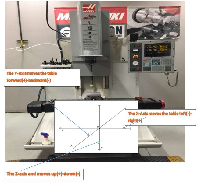
Figure 1. VMC Machine Motion
CNC Machine Coordinates
The CNC Machine Coordinate System is illustrated in Figure 11. The control point for the Machine Coordinate System is defined as the center-face of the machine spindle. The Origin point for the machine coordinate system is called Machine Home. This is the postion of the center-face of the machine spindle when the Z-axis is fully retracted and the table is moved to its limits near the back-left corner.
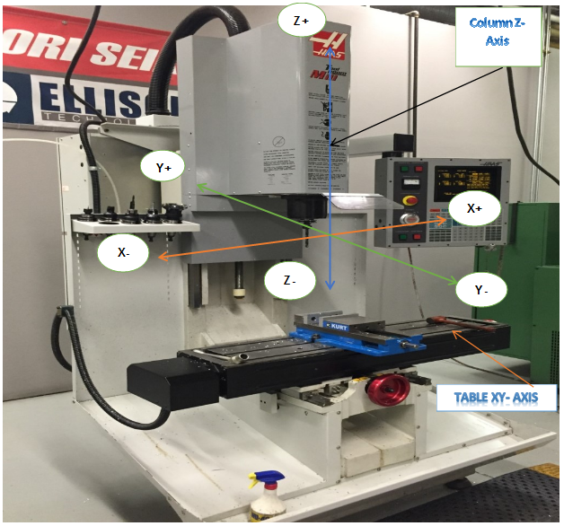
Figure 2. VMC Machine Coordinate System (At Home Position)
As shown in Figure 12, when working with a CNC, always think, work, and write CNC programs in terms of tool motion, not table motion. For example, increasing +X coordinate values move the tool right in relation to the table (though the table actually moves left). Likewise, increasing +Y coordinate values move the tool towards the back of the machine (the table moves towards the operator). Increasing +Z commands move the tool up (away from the table).
About Machine Home Position
When a CNC machine is first turned on, it does not know where the axes are positioned in the work space. Home position is found by the Power On Restart sequence initiated by the operator by pushing a button on the machine control after turning on the control power.
The Power On Restart sequence simply drives all three axes slowly towards their extreme limits (-X, +Y, +Z). As each axis reaches its mechanical limit, a microswitch is activated. This signals to the control that the home position for that axis is reached. Once all three axes have stopped moving, the machine is said to be “homed”. Machine coordinates are thereafter in relation to this home position.
Work Coordinate System
Obviously it would be difficult to write a CNC program in relation to Machine Coordinates. The home position is far away from the table, so values in the CNC program would be large and have no easily recognized relation to the part model. To make programming and setting up the CNC easier, a Work Coordinate System (WCS) is established for each CNC program.
The WCS is a point selected by the CNC programmer on the part, stock or fixture. While the WCS can be the same as the part origin in CAD, it does not have to be. While it can be located anywhere in the machine envelope, its selection requires careful consideration.
- The WCS location must be able to be found by mechanical means such as an edge finder, coaxial indicator or part probe.
- It must be located with high precision: typically plus or minus .001 inches or less.
- It must be repeatable: parts must be placed in exactly the same position every time.
- It should take into account how the part will be rotated and moved as different sides of the part are machined.
For example, Figure 13 shows a part gripped in a vise. The outside dimensions of the part have already been milled to size on a manual machine before being set on the CNC machine.
The CNC is used to make the holes, pockets, and slot in this part. The WCS is located in the upper-left corner of the block. This corner is easily found using an Edge Finder or Probe.
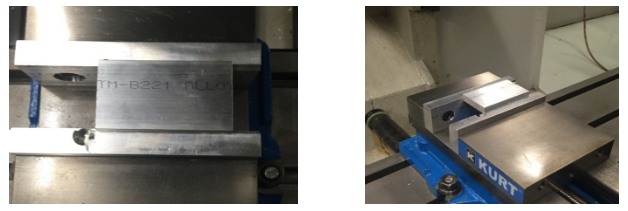
Top View Side View
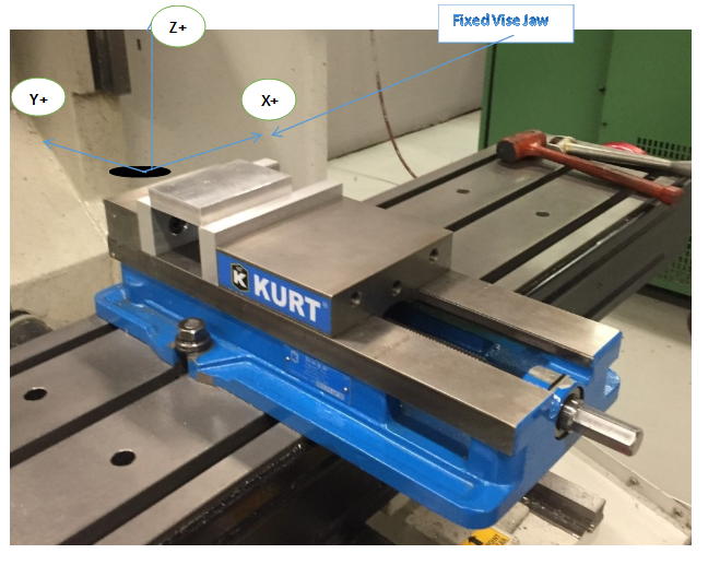
Figure 3. Work Coordinate System (WCS)
Machine and Tool Offsets
Machine Offsets:
Because it is difficult to place a vise in the exact same position on the machine each time, the distance from Home to the WCS is usually not known until the vise is set and aligned with the machine. Machine set up is best done after the program is completely written, because it is expensive to keep a CNC machine idle waiting for the CNC programming to be done. Besides, the programmer may change their mind during the CAM process, rendering any pre-planned setup obsolete.
To complicate matters further, different tools extend out from the machine spindle different lengths, also a value difficult to determine in advance. For example, a long end mill extends further from the spindle face than a stub length drill. If the tool wears or breaks and must be replaced, it is almost impossible to set it the exact length out of the tool holder each time.
Therefore, there must be some way to relate the Machine Coordinate system to the part WCS and take into account varying tool lengths. This is done using machine Tool and Fixture Offsets. There are many offsets available on CNC machines. Understanding how they work and to correctly use them together is essential for successful CNC machining.
Part Offset XY:
Fixture offsets provide a way for the CNC control to know the distance from the machine home position and the part WCS. In conjunction with Tool Offsets, Fixture Offsets allow programs to be written in relation to the WCS instead of the Machine Coordinates. They make setups easier because the exact location of the part in the machine envelop does not need to be known before the CNC program is written.
As long as the part is positioned where the tool can reach all machining operations it can be located anywhere in the machine envelope. Once the Fixture Offset values are found, entered into the control, and activated by the CNC program, the CNC control works behind the scene to translate program coordinates to WCS coordinates.
Notice in Figure 14 how Part Offsets (+X, -Y) are used to shift the centerline of the machine spindle directly over the WCS.
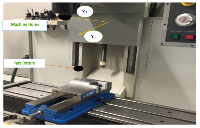
Figure 4: Part Offset Shifts Machine to WCS
Part Offset Z
The Part Offset Z value is combined with the Tool Length offset to indicate to the machine how to shift the Z-datum from part home to the part Z-zero, taking into account the length of the tool. Fixture Offset Z may or may not be used, depending on how the machine is set up and operated.
Tool Length Offset (TLO)
Every tool loaded into the machine is a different length. In fact, if a tool is replaced due to wear or breaking, the length of its replacement will likely change because it is almost impossible to set a new tool in the holder in exactly the same place as the old one. The CNC machine needs some way of knowing how far each tool extends from the spindle to the tip. This is accomplished using a Tool Length Offset (TLO).
In its simplest use, the TLO is found by jogging the spindle with tool from the machine home Z-position to the part Z-zero position, as shown on the far left in Figure 17 below. The tool is jogged to the part datum Z and the distance travelled is measured. This value is entered in the TLO register for that tool. Problems with this method include the need to face mill the part to the correct depth before setting tools. Also, if the Z-datum is cut away (typical of 3D surfaced parts) it is impossible to set the datum should a tool break or wear and need to be replaced. All tools must be reset whenever a new job is set up. When this method is used, the Fixture Offset Z is not used, but set to zero.
The method shown in the center is much better and used in this book. All tools are set to a known Z-position, such the top of a precision 1-2-3 block resting on the machine table. This makes it very easy to reset tools if worn or broken.
A tool probe is very similar to the 1-2-3 block method, except the machine uses a special cycle to automatically find the TLO. It does this slowly lowering the tool until the tip touches the probe and then updates the TLO register. This method is fast, safe and accurate but requires the machine be equipped with a tool probe. Also, tool probes are expensive so care must be taken to never crash the tool into the probe.
Both the 2nd and 3rd methods also require the distance from the tool setting position (the top of the 1-2-3 block or tool probe) to the part datum to be found and entered in the Fixture Offset Z. The machine adds the two values together to determine the total tool length offset. A method for doing this is included in.
3-Ways to Set Tool Length Offset
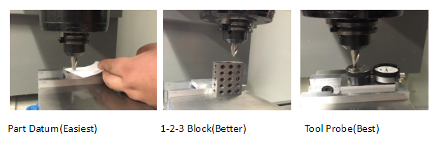
Figure 5. Ways to set TLO
UNIT TEST
1. Explain Machine home position.
2. On the Vertical Milling Center(VMC) the X axis move the table in what direction.
3. On the Vertical Milling Center(VMC) the Y axis move the table in what direction.
4. On the Vertical Milling Center(VMC) the Z axis move the table in what direction.
5. Please lists 3-ways to set Tool length offsets.
