9 Unit 4: Turning
OBJECTIVE
After completing this unit, you should be able to:
• Describe the rough and finishing turning.
• Describe the turning shoulder.
• Describe the facing cut.
• Explain how to set up for center/spot drill.
• Explain how to set up for boring.
• Explain how to set up for knurling.
• Correctly set up a workpiece for parting/grooving.
• Determine the taper calculation.
• Correctly set up workpiece in a 4-jaw chuck.
Workpiece is generally machined on a lathe for two reasons: to cut it to size and to produce a true diameter. Work that must be cut to size and have the same diameter along the entire length of the workpiece involves the operation of parallel turning. Many factors determine the amount of materials which can be removed on a lathe. A diameter should be cut to size in two cuts: an roughing cut and finishing cut.
To have the same diameter at each end of the workpiece, the lathe centers must be in line.
To set an accurate depth of cut
Procedure:
1. Set the compound rest at 30 degrees.
2. Attach a roughing or finishing tool. Use a right-handed turning tool if feeding the saddle in the direction of the headstock.
3. Move the tool post to the left hand side of the compound rest and set the tool bit to right height center.
4. Set the lathe to the correct speed and feed for the diameter and type of material being cut.
5. Start the lathe and take a light cut about .005 inch and .250 inch long at the right hand end of the workpiece.
6. Stop the lathe, but do not move the crossfeed screw handle.
7. Move the cutting tool to the end of the workpiece (to the right side) by turning the carriage hand wheel.
8. Measure the work and calculate the amount of material to be removed.
9. Turn the graduated collar half the amount of material to be removed. For example, if .060 inch to be removed, the graduated collar should be turned in .030 inch, since the cut is taken off the circumference of the workpiece.
10. Remember, for each thousandth depth of cut, the diameter of the stock is reduced by two thousandths.
Rough Turning
The operation of rough turning is used to remove as much metal as possible in the shortest length of time. Accuracy and surface finish are not important in this operation. Therefore, max depth of .030 inch and a .020 to .030 inch feed is recommended. Workpiece is generally rough turned to within about .030 inch of the finished size in a few cuts as possible.
Procedure:
1. Set the lathe to the correct speed and feedrate for the type and size of the material being cut.
2. Adjust the quick change gear box for a .010 to .030 inch feed, depending on the depth of cut and condition of the machine.
3. For Example: .010
4. Move the tool holder to the left hand side of the compound rest and set the tool bit to right height to center.
5. Tighten the tool post securely to prevent the toolholder from moving during the machining operation.
6. Take a light trial cut at the right hand end of the workpiece for about .250 inch length.
7. Measure the workpiece and adjust the tool bit for the proper depth of cut.
8. Cut along for about .250 inch, stop the lathe and check the diameter for size. The diameter should be about .030 inch over the finish side.
9. Re-adjust the depth of cut, if necessary.
Finish Turning
Finish turning on a lathe, which follows rough turning , produces a smooth surface finish, and cuts the workpiece to an accurate size. Factors such as the condition of the cutting tool bit, the rigidity of the machine and workpiece and the lathe speed and feedrate, may affect the type of surface finish produced.
Procedure:
1. Check to see if the cutting edge of the tool bit is free from nicks, burns, etc. It is good practice to home the cutting edge before you take a finish cut.
2. Set the lathe to the recommended speed and feedrate. The feed rate used depends upon the surface finish required.
3. Take a light trial cut about .250 inch long at the right hand end of the work to produce a true diameter, set the cutting tool bit to the diameter and set the graduated collar to the right diameter.
4. Stop the lathe, measure the diameter.
5. Set the depth of cut for half the amount of material to be removed.
6. Cut along for .250 inch, stop the lathe and check the diameter.
7. Re-adjust the depth of cut, if necessary and finish turn the diameter. In order to produce the truest diameter possible, finish turn workpiece to the required size. Should it be necessary to finish a diameter by filming or polishing, never leave more than .002 to .003 inch for this operation.
Turning to a Shoulder
When turning more than one diameter on a workpiece. The change in diameter or step, is known as shoulder.
Three common types of shoulder:
1. Square
2. Filleted corner
3. Angular of Tapered
Procedure:
1. With a workpiece mounted in a lathe, lay out the shoulder position from the finished end of the workpiece. In case of filleted shoulders, all sufficient length to permit the proper radius to be formed on the finished shoulder.
2. Place the point of the tool bit at this mark and cut a small groove around the circumference to mark off the length.
3. With a turning tool bit, rough and finish turn the workpiece about .063 inch of the required length.
4. Set up an end facing tool. Chalk the small diameter of the workpiece, and bring the cutting tool up until it just removes the chalk mark.
5. Note the reading on the graduated collar of the cross feed handle.
6. Face square the shoulder, cutting to the line using hand feed.
7. For successive cuts, return the cross feed handle to the same graduated collar setting.
If a filleted corner is required, a tool bit having the same radius is used for finishing the shoulder. Angular or chamfered edges may be obtained by setting the cutting edge of the tool bit to the desired angle of chamfer and feeding it against the shoulder, or by setting the compound rest to the desired angle.
Facing
Workpieces to be machined are generally cut a little longer than required, and faced to the right length. Facing is an operation of machining the ends of a workpiece square with its axis. To produce a flat, square surface when facing, the lathe might be true.
The purpose of facing are:
• To provide a true, flat surface, square with the axis of the workpieces.
• To provide and accurate surface from which to take measurements.
• To cut the workpieces to the required length.

Figure 1. Facing Operation
Procedure:
1. Move the tool post to the left-hand side of the compound rest, and set the right hand facing tool bit to the right height of the lathe center point. The compound rest may be set at 30 degrees for accurate end facing.
2. Mount the workpiece in the chuck to face. Use a line center in the tail stuck or straight ruler if needed for true.
3. Insert a facing tool.
4. Position the tool slightly off from the part.
5. Set the facing tool bit pointing left at a 15-20 degree angle. The point of the tool bit must be closest to the workpiece and space must be left along the side.
6. Set the lathe to the correct speed and feed for the diameter and type of material being cut.
7. Before turning the machine on, turn the spindle by hand to make sure parts do not interfere with spindle rotation.
8. Start the lathe and bring the tool bit ad close to the lathe center as possible.
9. Move the carriage to the left, using the handwheel, until the small cut is started.
10. Feed the cutting tool bit inwards to the center by turning the cross feed handle. If the power feed cross feed is used for feeding the cutting tool, the carriage should be locked in position.
11. Repeat procedure 6,7 and 8 until the workpiece is cut to the correct length. 12. There will be a sharp edge on the workpiece after facing, which should be broken with a file.
To spot a workpiece
Spotting Tool bit is used to make a shallow, v-shaped hole in the center of the workpiece. Provides a guide for the drill to follow. A hole can be spotted quickly and fairly accurately by using a center drill. A spotting tool bit should be used for extreme accuracy.

Figure 2: Center/Spot Tool
Procedure:
1. Mount workpiece true in a chuck.
2. Mount the drill chuck into the tailstock.
3. Ensure that the tang of the drill chuck is properly secured in the tailstock.
4. Move and lock the tailstock to the desired position.
5. Before turning the machine on, turn the spindle by hand to make sure parts do not interfere with spindle rotation.
6. Set the lathe to the proper speed for the type of material to be spot or center drill.
7. Start the hole using a center drill. 8. Spot the hole with a spotting or center drill tool bit.
Drilling
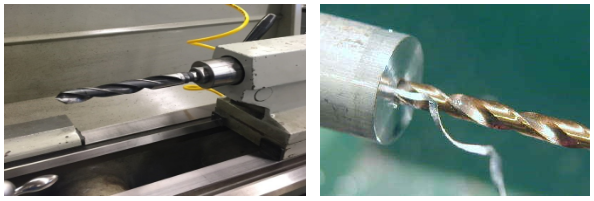
Figure 3. Drill
Procedure:
1. Mount the drill chuck into the tailstock.
2. Mount workpiece true in a chuck.
3. Check the tool stock center and make sure it is in line.
4. Ensure that the tang of the drill chuck is properly secured in the tailstock.
5. Move and lock the tailstock to the desired position.
6. Before turning the machine on, turn the spindle by hand to make sure parts do not interfere with spindle rotation.
7. Start the hole using a spotting or center drill tool bite.
8. When using a center drill, always use cutting fluid along with it.
9. A center drill doesn’t cut as easily as a drill bit would, as it has shallow flutes for added stiffness.
10. Drill past the entirety of the taper to create a funnel to guide the bit in.
11. Mount the drill in the tailstock spindle, in a drill chuck or in a drill holder.
12. Set the lathe to the proper speed the type of material to be drilled.
13. Start the lathe and drill to the desired depth according to the blueprint drawing, applying cutting fluid.
14. To gauge the depth of the hole, use the graduations on the tailstock spindle, or use a steel rule to measure the depth.
15. Use the peck drill operation to remove the chips and measure the depth of the hole.
16. When drilling, take off at most one or two drill bit diameters worth of material before backing off, clearing chips, and reapplying cutting fluid.
17. If the drill bit squeaks against the stock, apply more cutting fluid.
18. To remove the drill chuck from the tailstock, draw it back by around a quarter turn more than it will easily go.
19. Use a pin to press the chuck out of the collet.
Boring
Boring is an operation to enlarge and finish holes accurately. Truing of a hole by removing material from internal surfaces with a single point tool bit cutter. Special diameter holes, for which no drills are available, can be produced by boring.
Boring utilizes a single point cutting tool to enlarge a hole. This operation provides for more accurate and concentric hole, as opposed to drilling.
Since the cutter extends from the machine from a boring bar, the tool is not as well-supported, which can result in chatter. The deeper the boring operation, the worse the chatter. To correct this:
1. Reduce the spindle speed.
2. Increase the feed.
3. Apply more cutting fluid.
4. Shorten the overhang of the boring bar.
5. Grind a smaller radius on the tool’s nose.
Procedure:
1. Mount the workpiece in a chuck.
2. Face, spot and drill the hole on the workpiece.
3. Check to see if the boring bar has enough clearance.
- If the hole is too small for the boring bar, the chips will jam while machining and move the bar off-center.
4. Make sure that the point of the boring tool is the only part of the cutter than contacts the inner surface of the workpiece.
5. If the angle does not provide sufficient end relief, replace the cutter with one that has a sharper angle.
6. Position the boring bar so the point of the cutter is positioned with the centerline of the stock.
7. A tool that is not placed in line with the center of the workpiece will drag along the surface of stock, even if there is a sufficient end relief angle.
8. Select a boring bar as large as possible and have it extend beyond the holder only enough to clear the depth of the hole to be bored.
9. Mount the holder and boring tool bar with the cutter tool bit on the left hand side of the tool post and revolving the workpiece.
10. Set the boring tool bit to center.
- Note: Depending on the rigidity of the setup, the boring tool bit will have a tendency to spring downward as pressure is applied to the cutting edge. By setting the boring tool bit slightly above center, compensation has been made for the downward spring and the tool bit will actually be positioned on the exact center of the workpiece during machining operations.
11. Set the lathe to the proper cutting speed and feed. a. Note: For feedrate select a medium feed rate.
12. Apply lube to the hole before turning the machine on.
13. Turn the machine on and move the tool into the pre-drilled hole.
14. Start the lathe and slowly bring the boring tool until it touch the inside diameter of the hole.
15. Take a light cut (about .003 in.) and about -375 long.
16. Stop the lathe and measure the hole diameter, use a telescopic gauge or inside micrometer.
17. After measure the hole, determine the amount of material to be removed from the hole. Leave about .020 in a finish cut.
18. Start the lathe and take the roughing cut.
19. Feed the boring bar into the workpiece, taking off about .020 on each pass.
20. Bring the boring bar out once the desired depth has been reached.
21. Repeat steps 19 and 20 until the desired diameter of the inside hole has been attained.
22. After roughing cut is completed, stop the lathe and bring the boring tool bit out of the hole without moving the cross feed handle.
23. Set the depth of the finish cut and bore the hole to size. For a good surface finish, a fine feedrate is recommended.
24. On the last pass, stop at the desired depth and bring the cutter back towards the center of the stock. This will face the back of the hole.
25. Bring the boring bar out of the machine and stop the machine.

Figure 4. Boring on a lathe
Knurling
1. A knurl is a raised impression on the surface of the workpiece produced by two hardened rolls.
2. Knurls are usually one of two patterns: diamond or straight.
3. Common knurl patterns are fine, medium, or coarse.
4. The diamond pattern is formed by a right-hand and a left-hand helix mounted in a self-centering head.
5. Used to improve appearance of a part & provide a good gripping surface for levers and tool handles.
6. Common knurl patterns are fine, medium, or coarse.
7. The straight pattern, formed by two straight rolls, is used to increase the size of a part for press fits in light-duty applications.
8. Three basic types of knurling toolholders are used: the knuckle-joint holder, the revolving head holder, and the straddle holder.
9. Knurling works best on workpieces mounted between centers.
10. Knurls do not cut, but displace the metal with high pressure.
11. Lubrication is more important than cooling, so a cutting oil or lubricating oil is satisfactory.
12. Low speeds (about the same as for threading) and a feed of about .010 to .020 in. are used for knurling.
13. The knurls should be centered on the workpiece vertically & the knurl toolholder square with the work.
14. A knurl should be started in soft metal about half depth and the pattern checked.
15. Several passes may be required on a slender workpiece to complete a knurl because the tool tends to push it away from the knurl.
16. Knurls should be cleaned with a wire brush between passes.

Figure 5. Knurling
Procedure:
1. Mount the knurling tool into a tool holder and and adjust it to the exact centerline of the lathe spindle.
2. Position and secure the knurling tool 90 degrees to the surface of the knurled.
3. Move the lathe carriage by hand and locate the area on the workpiece to be knurled.
4. Rotate the knurling head to index to the correct set knurls.
5. Position the knurls to the right edge of work such that half of the knurl contacts the right edge of the workpiece.
6. Apply cutting oil to the work.
7. Turn the spindle to about 100 RPM and use the crossfeed handwheel to move the knurling tool into the work. This should be approximately 0.030 inches, or until knurls track and form a good pattern.
8. Engage the lathe power feed to move the carriage towards the headstock at a feedrate of 0.010 to 0.020 inches per revolution.
9. Apply oil as required and brush knurled area with a stiff brush to clean chips from knurl.
10. When the knurls reach the end of knurled area, reverse the carriage feed direction feed direction and feed knurls into the work another 0.005 to 0.010 inches.
11. Continue knurling back and forth until a sharp diamond develops.
Parting and Grooving on a Lathe
The purpose of parting and grooving:
There are times when you may want to cut a piece from the end of a workpiece, or you may want to cut a groove into a workpiece.
Grooving, commonly called recessing, undercutting, or necking, is often done at the end of a thread to permit full travel of the nut up to a shoulder or at the edge of a shoulder to ensure a proper fit of mating parts. There are three types of grooves: square, round, and u-shaped.
Rounded grooves are usually used where there is a strain on the part, and where a square corner would lead to fracturing of the metal.
To cut a Groove
Procedure:
1. Select a tool bit to the desired size and shape of the groove required.
2. Lay out the location of the groove.
3. Set the lathe to half the speed for turning.
4. Mount the workpiece in the lathe.
5. Set the tool bit to center height.
6. Slowly feed the tool bit into the workpiece using the cross feed handle.
7. Apply plenty of cutting oil to the point of the cutting tool. To ensure that the cutting will not blind in the groove. If chatter develops, reduce the spindle speed.
8. Stop the lathe and check the depth of groove.
9. Repeat procedures 6-7 until the work is cut to the correct depth.

Figure 6. Cutting a Groove
Parting
Cut off tools, often called parting tools, are used for cutting workpiece. There are three types of parting tools. The parting tool consists of a straight holder, left hand offset and right hand offset inserted blade are the most commonly used.
There are two common problems in parting, chattering and hugging in. A chattering occurs when the tool is not held solidly enough, any looseness in the tool, holder, or any part of the lathe itself makes cutting off difficult, uneven, and often impossible. Hugging in means the tool tends to dig into the workpiece tends to climb over the top of the cutting edge. This usually breaks off the tool bit or wrecks the workpiece. Hugging in is usually caused when the parting tool is set too high or too low.
• Parting tools are narrower but deeper than turning tools. Parting tools are used to create narrows grooves and cut off parts of the stock.
• The tool holder should barely clear the workpiece when the parting tool is installed.
• Make sure the parting tool is perpendicular to the axis of rotation.
• Ensure the tip of the tool rests at the same height as the center of the stock. Holding the tool against the face of the part may help with this.
• Set the tool’s height, lay it against the part’s face, and lock the tool in place. Remember to apply cutting fluid, especially when making a deep cut.

Figure 7. Parting
Procedure:
1. Mount the workpiece in the chuck with the part to be cut off as close to the chuck as possible.
2. Mount the parting tool on the left hand side of the compound rest with the cutting edge set on center.
3. Place the holder as close to the tool post as possible to prevent vibration and chatter.
4. Adjust the tool bit. The tool bit should extend from the holder a distance equal to little more than half the diameter of the workpiece. Adjust the revolution per minute (rpm) to about ⅔ the speed for turning.
5. Mark the location of the cut.
6. Move the cutting tool into position.
7. Start the lathe and slowly feed the parting tool into workpiece by hand. Grip the cross feed handle with both hands in order to feed steadily and uniformly. Apply plenty of cutting oil.
8. When the workpiece is about ¼ in, it is good practice to move the parting tool sideways slightly. This side motion cut a little wider to prevent the tool from jamming.
9. To avoid chatter, keep the tool cutting and apply cutting oil consistently during the operation. Feed slowly when the part is almost cut off.
10. Keep advancing the tool until it reaches the center of the workpiece. As you get close, the workpiece is suspendend by a thin stalk of metal.
11. The end of the workpiece that you cut off will generally have a pretty rough finish and a little stalk of metal protruding from the end. See figure 19 below.
12. The final step it to mount this piece in the chuck and make a facing cut to clean up the end. One problem with this step is that the chuck jaws can mar the finished workpiece. If you look carefully at figure 20 below you can actually see the imprint of the chuck jaws. To avoid this, you could wrap the workpiece in a thin strip of emory paper, or similar protective material, before clamping it.

Figure 8. Workpiece Cutoff Figure 9. Finished Workpiece
Alignment of Lathe Centers
To produce a parallel diameter when machining work between centers, it is important that is, the two lathe centers must be in line with each other and running true with the centerline of the lathe. If the center are not aligned, the work being machined will be tapered.
There are three methods to align lathe centers:
1. By aligning the centerlines on the back of the tail stock with each other. This is only a visual check and therefore not for accurate.
2. The trial cut method, where a small cut is taken from each end of the work and the diameter are measured with a micrometer.
3. Align Centers using a Dial Indicator.
Method 1. To align centers by adjusting the tailstock.
Procedure:
1. Loosen the tailstock clamp not or lever.
2. Loosen one of the adjusting screw on the left or right side, depending upon the direction the tail stock must be moved. Tighten the other adjusting screw until the line on the top half of the tail stock aligns exactly with the line on the bottom half.
3. Tighten the loosened adjusting screw to lock both halves of the tailstock in place.
4. Lock the tailstock clamp nut or lever.
Method 2. To align center by the trail cut method.
Procedure:
1. Take a light cut about .010 to a true diameter, from section A at the tailstock end of .250 inch long.
2. Stop the feed and note the reading on the graduated collar of the cross feed handle.
3. Move the cutting tool close to the headstock end.
4. Bring the cutting tool close to the same collar setting as step 1 (Section A).
5. Return the cutting tool to the same collar setting as step 1. (Section A)
6. Cut a .250 length at Section B and then stop the lathe.
7. Measure both diameters with a micrometer.
8. If both diameters are not the same size, adjust the tailstock either toward or away from the cutting tool one-half the difference of the two readings.
9. Take another light cut at Section A and B. Measure these diameters and adjust the tailstock, if required.
Method 3. To Align Centers using a Dial Indicator.
Procedure:
1. Clean the lathe and work centers and mount the dial indicator.
2. Adjust the test bar snuggly between centers and tighten the tailstock spindle clamp.
3. Mount a dial indicator on the tool post or lathe carriage. Be sure that the indicator plunger is parallel to the lathe bed and that the contact point is set on center.
4. Adjust the cross slide so that the indicator registers about .025 inch at the tailstock end.
5. Move the carriage by hand so the test indicator registers on the diameter at the headstock end and note the test indicator reading.
6. If both test indicator readings are not the same. Adjust the tailstock by the adjusting screw until the indicator registers the same reading at both ends.
Taper Calculations
To calculate the taper per foot (tpf). It is necessary to know the length of the taper, large and small diameter.
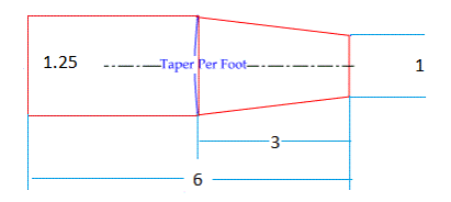
Figure 10. The main part of an inch taper
Formula:
Tpf = ((D-d) / length of taper) x 12
Example:
Tpf = ((1.25 – 1) / 3) x 12 = (.25 / 3) x 12 = 1 in.
Tailstock Offset Calculations
When calculating the tail stock offset, the taper per foot and total length of the workpiece must be known.
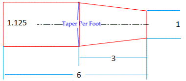
Figure 11. Dimension of a workpiece having a taper
Formula:
Tailstock offset = (tpf x total length of workpiece) / 24
Example:
1. Find tpf:
tpf = ((1.125 – 1) x 12) / 3 = (.125 x 12) / 3 = .50 in.
2. FInd the Tailstock offset:
Tailstock offset = (.5 x 6) / 24 = 3 / 24 = .125 in.
In some case where it is not necessary to find the taper per foot, the following simplified formula can be used.
Formula:
Tailstock Offset = (OL / TL) x ((D-d) / 2)
OL = Overall length of workpiece
TL = length of the tapered section
D = large diameter end
d = small diameter end
Example:
Tailstock Offset = (6 / 3) x ((1.125-1) / 2) = .125
Taper Turning
Using the compound rest to produce short or steep tapers. The tool bit must be fed in by hand, using the compound rest feed handle.
Cut a taper producer with Compound rest
Procedure:
1. Refer to the blueprint drawing for the amount of the taper required in degrees.
2. Loosen the compound rest lock screws.
3. Swivel the compound rest to the angle desired. (See first Picture)
4. Tighten the compound rest lock screws.
5. Adjust the tool bit on center and feed the cutting tool bit, using the compound rest feed screw.
6. Check the taper for size and fit.
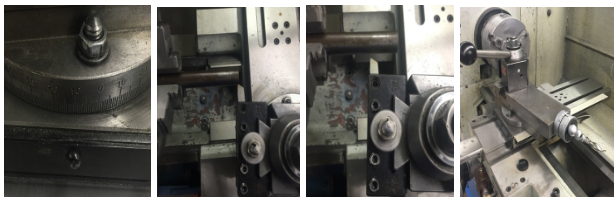
Figure 12. Taper Turning Operation
True workpiece in a 4-jaw chuck
1. A dial or test indicator should be used whenever a machined diameter must be aligned to within a thousandths of an inch.
2. Procedure:
3. Insert the workpiece in the 4-jaw chuck and true it approximately, using either the chalk or surface gauge method.

4. Mount an indicator, in the tool post of the lathe.

5. Set the indicator spindle in a horizontal position with the contact point set to the center height.

6. Bring the indicator point against the workpiece diameter so that it registers about .020 and rotate the lathe spindle by hand.
7. As you revolve the lathe, note the highest and lowest reading on the dial indicator.
8. Slightly loosen the chuck jaw at the lowest reading, and tighten the jaw at the high reading until the work is moved half the difference between the two indicator readings.
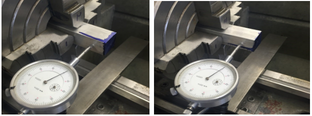
Side 1. Left and Right Side
9. Continue to adjust only these two opposite jaws until the indicator registers the at both jaws. Disregard the indicator readings on the work between these two jaws.
10. Adjust the other set of opposite jaws in the same manner until the indicator register the same at any point on the workpiece circumference.
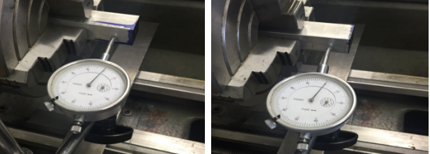
Side 2. Left and Right Side
11. Tighten all jaws evenly to secure the workpiece firmly.
12. Rotate the lathe spindle by hand and recheck the indicator reading.
UNIT TEST
1. The compound rest is set at what angle?
2. Explain the different between rough and finish turning.
3. Should the point of the tool be set above, or at the center of the spindle axis when taking a facing cut?
4. What is the purpose of facing?
5. Why do we spot drill a workpiece?
6. What is the purpose of boring?
7. Name three types of parting tools.
8. Name three methods to align lathe centers.
9. Calculate the offset for the taper if D=2, d=1, OL=6, and TL=3. The formula is:
Offset = (OL x (D-d)) / (2 x TL)
10. Please describe the producer for cut a taper.

