7 Groove Welding Symbols
A groove weld will be used when to parts come together in the same plane. These welds will be applied in a butt joint and may have a preparation or not before welding. This is the reason there are several types of groove welding symbols.
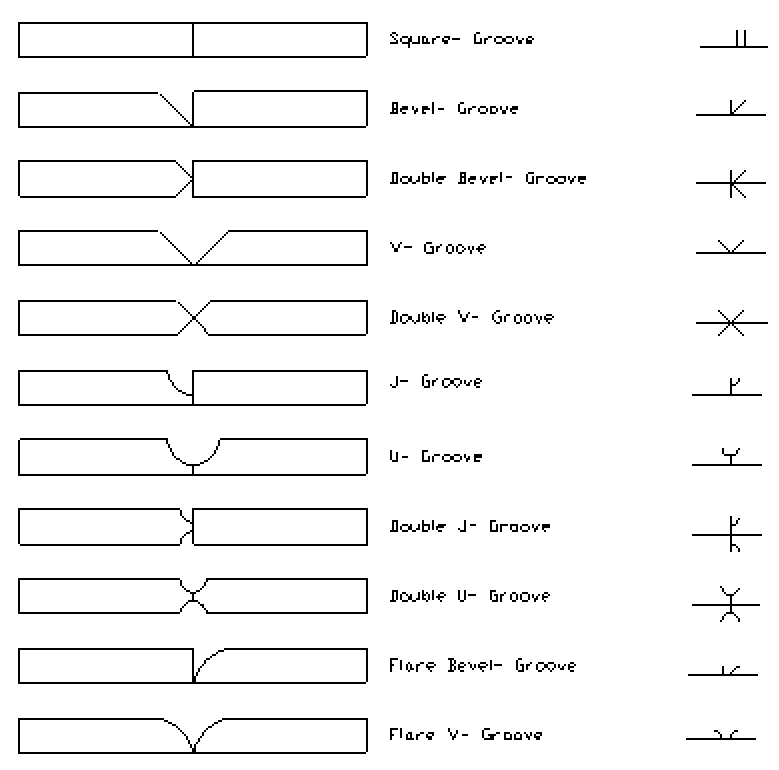
The symbols for these grooves are nearly identical to the symbols that represent them.
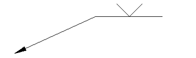
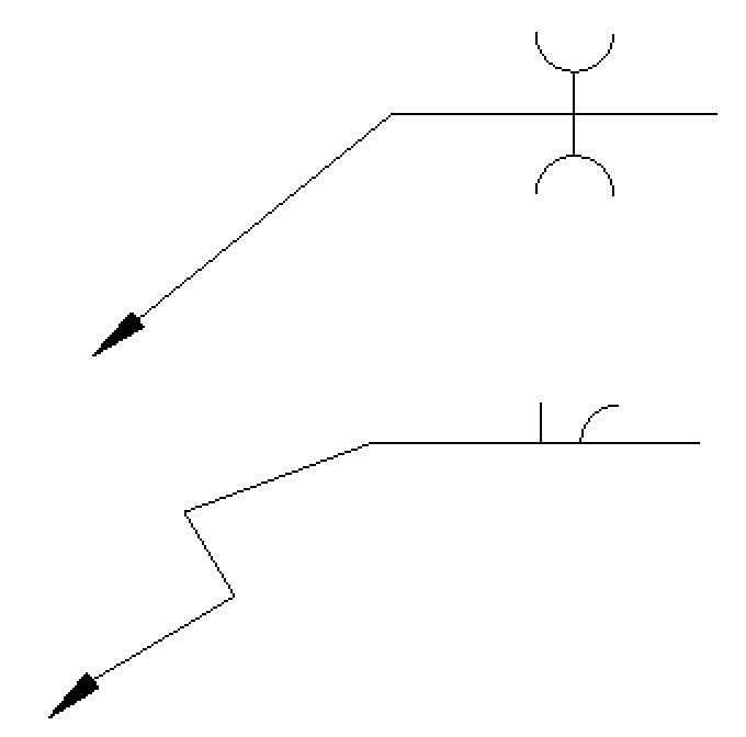
When a weld is to be applied to only one side of a joint it will be called a single groove weld. For example below is a welding symbol of a single V-Groove weld on the other side. All single groove welds should be considered complete joint penetration (CJP) unless otherwise specified.
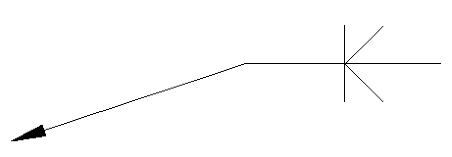
If a weld is to be applied to both sides of the joint this is called a double groove weld. For example below is a welding symbol of a double bevel groove weld.
The theory behind the single groove weld and double groove weld translate to all of the groove weld symbols. It would be redundant to recreate all of these images.
 What do these symbols call for?
In some cases you will see a jog in the arrow. This is called a break in the arrow that will designate which side of the joint will be required to have the preparation done to it. For example if a single bevel is to be applied to the left side of the joint a broken arrow will be pointing specifically at that side of the joint.
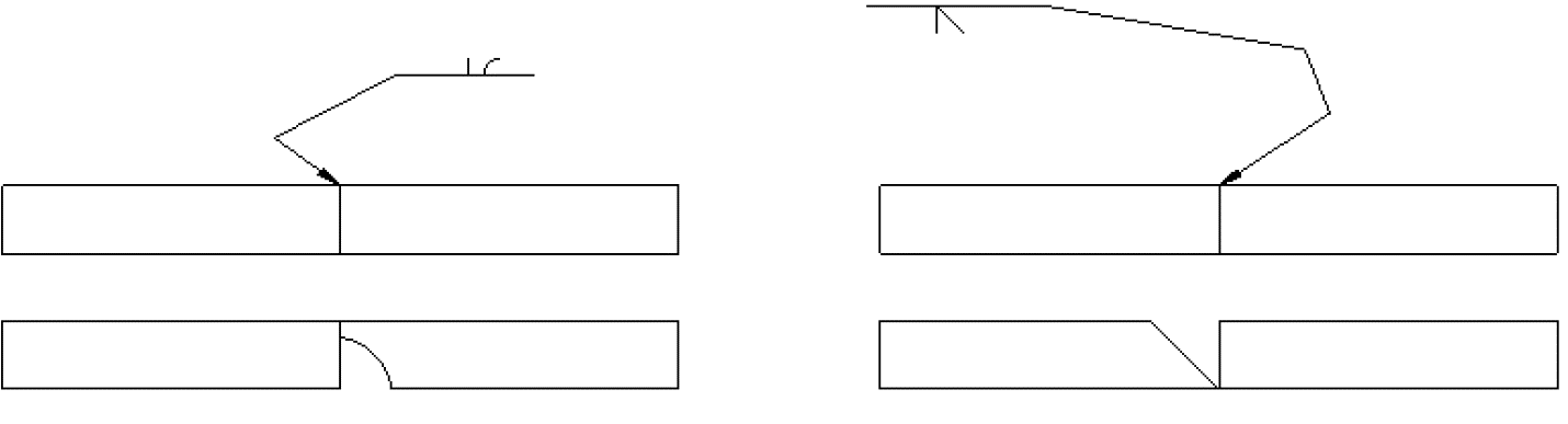
If there was not an indicating arrow the welder or fitter would choose which side should be prepared according to their knowledge. This could be an issue if an engineer has specific needs for the part or weld.
Quiz
Draw the symbol representing the below groove and name it (don’t forget to specify which side of the joint is prepared):
Draw the symbol for a V groove on the other side below:
Groove weld dimensioning
There are several dimensions that may be added to a groove weld if it is needed. This can include a groove angle, root opening, a groove radius, depth of the groove preparation, and groove weld size. There are times that this information may not be included at all. This would mean that it is the welder’s discretion as to how the part will be prepared and welded.
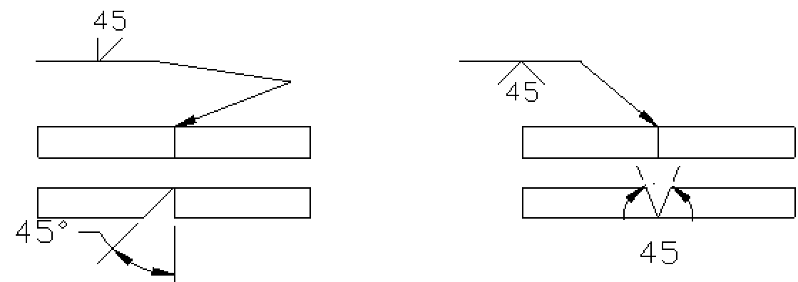
Groove angle is shown in degrees and will include all of the groove, if it is a V Groove it will be a dimension from one groove face to the other. This can be confused with bevel angle. Bevel angle is only one half of a V groove. This dimension is shown within the weld symbol itself. There is a possibility for two different angles if you are applying to a double groove weld. The arrow and other side do not have to necessarily match in angles.
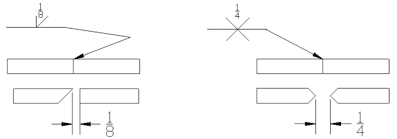
A groove weld is the most common weld to have a root opening. This is a gap that is predetermined to have between two members to be welded. There is not always a root opening and this dimension can be omitted from the welding symbol. It is common to put a root opening on a part to ensure complete penetration or even melt through. The melt through symbol is included in supplementary welding symbols.
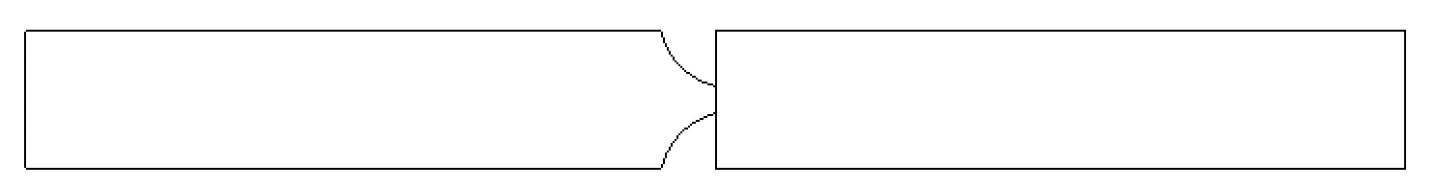
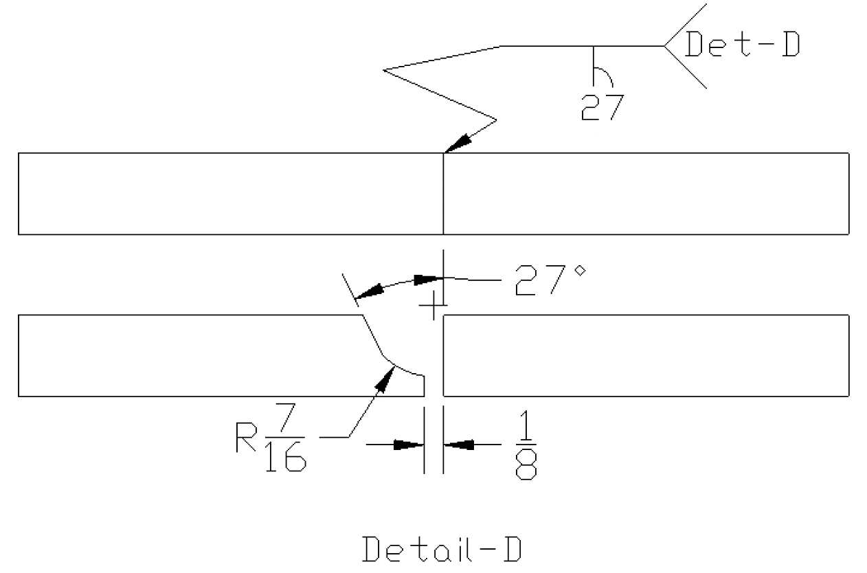
Grooves that associate with U and J preparations are a rather special weld. These welds if done to correct standards are machined with a specific radius of groove as well as root face. These dimensions must be shown in a detail or section view that is noted in the tail of the welding symbol.
The preparation of the groove may be called out for how deep you are to prepare the part. This is called the depth of groove. V- Grooves, j- grooves, and u- grooves are the most commonly sized welds for depth. Although this does not mean it cannot be applied to others. The dimension will be shown to the left of the weld symbol.
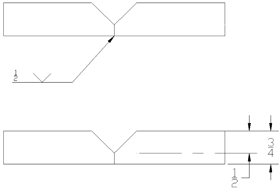
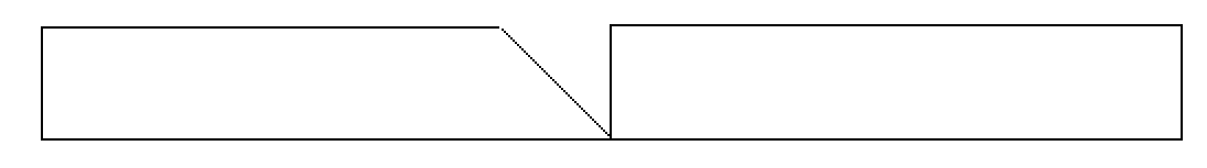
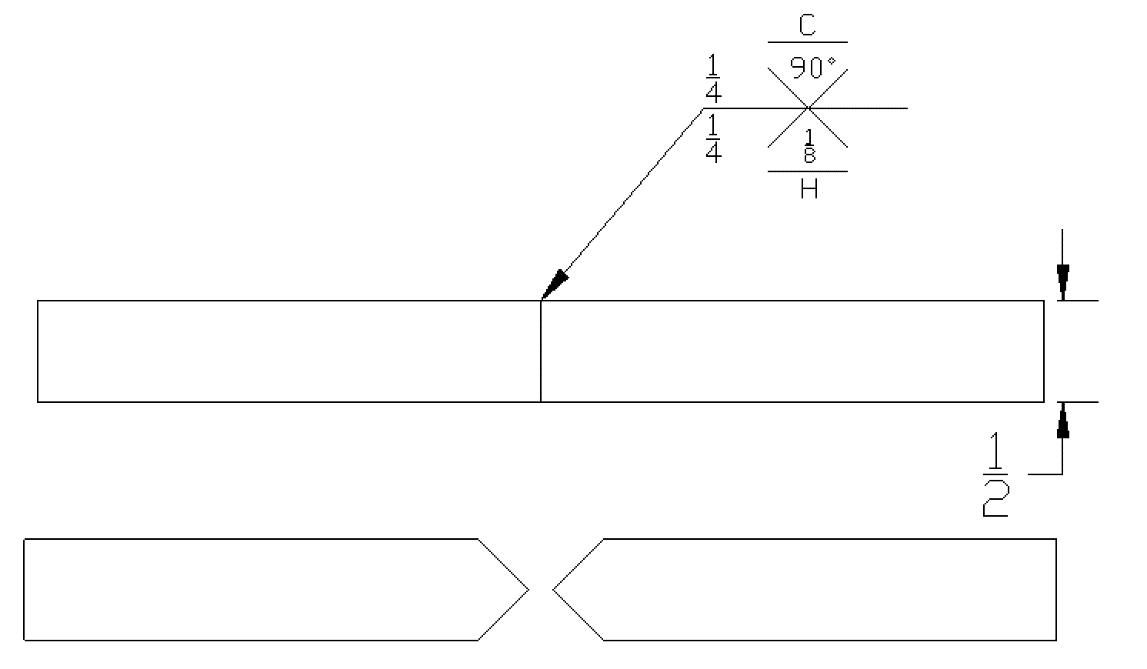
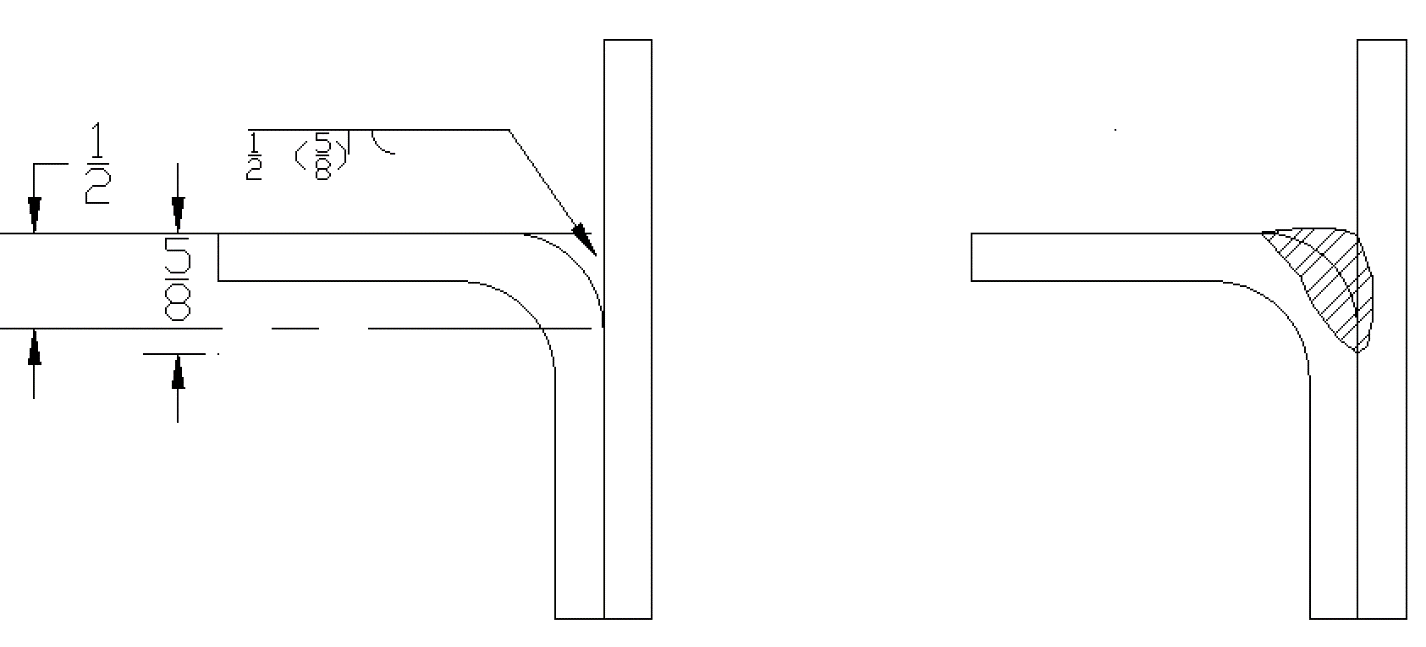
As we start adding more elements the symbols get fairly complicated looking. The easiest thing to do is slow down and look at each individual piece and apply it to what we have learned. For example the below weld is a single V-groove weld on the other side. This weld has a ½ inch groove depth, 1/16inch root opening, and 90 degree groove angle.
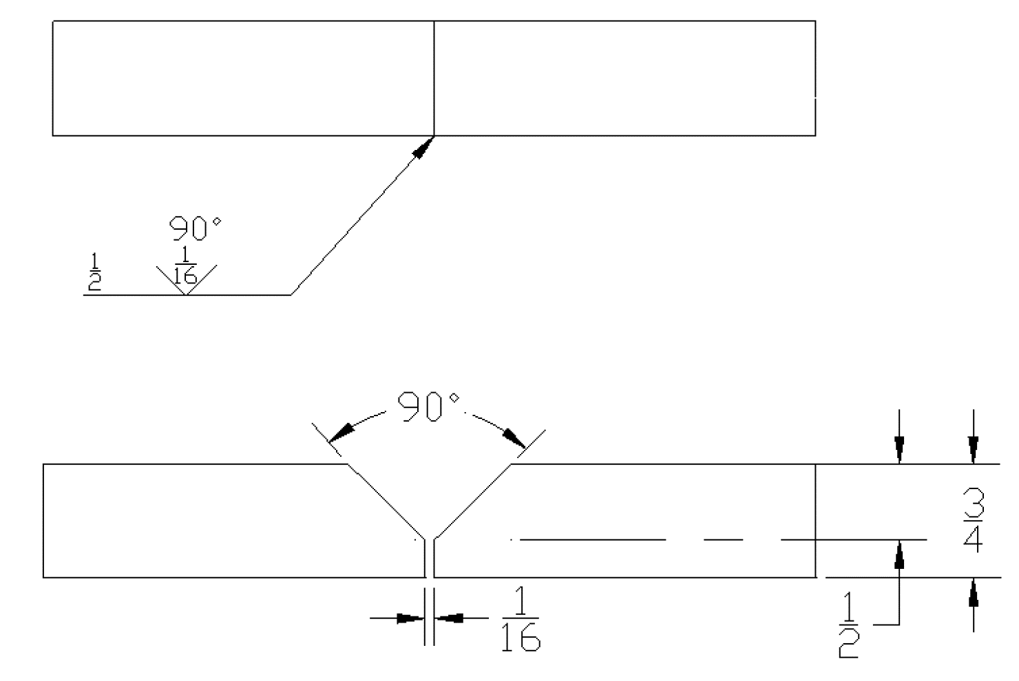
When using a groove depth that is not the full depth of the part we leave a flat area in the root. This area is called the root face. A more common term you will hear is the land. In the diagram above we have a ½ inch groove depth and we have a ¾ inch part. This leaves us a ¼ inch root face.
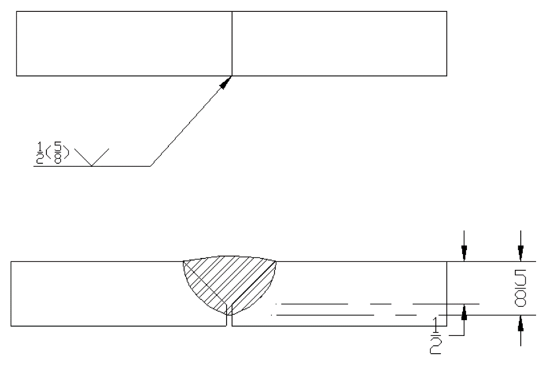
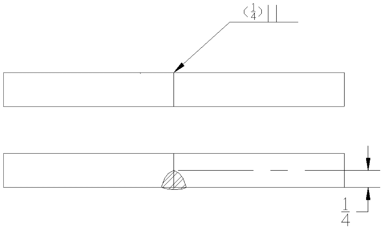
Often associated with a groove weld is going to be the weld size. This weld size is the depth of penetration you will be getting when applying the weld. When a weld is applied we should be melting into the root of the part so our weld should be larger in dimension than the preparation of the joint. This dimension will show to the left of the weld symbol. When paired with a groove depth the weld size will be within parentheses. If no weld size is shown the weld should be complete joint penetration.
In the case of a groove that shows a depth of groove preparation but the weld size does not show. The weld shall not be less than the depth of preparation. If you did not perform a weld that was at least this size you will not have completed adequate fusion or the weld will not fill the groove.
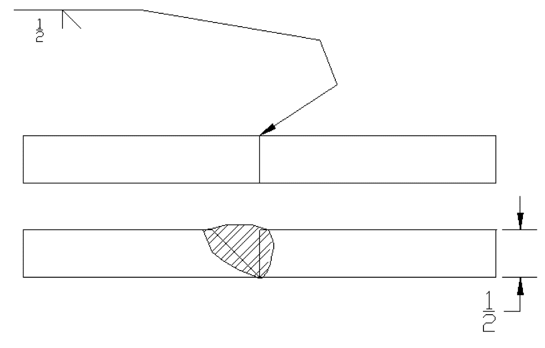
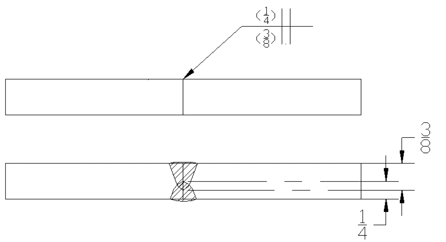
There are times when dimensions will not be shown on grooves. If the joint is symmetrical then the weld shall be complete joint penetration. This is easily pictured with a double v-Groove.
The above image shown is a double V-Groove weld. There is no groove depth shown so by welder’s discretion the parts are prepped to ¼ inch on both sides to create a symmetrical joint.
When working with a double groove that has the same dimensions on both sides it is required that dimensions are shown on both sides of the reference line. This is important because if one dimension is left off there will be an unknown size and this may compromise the weld.
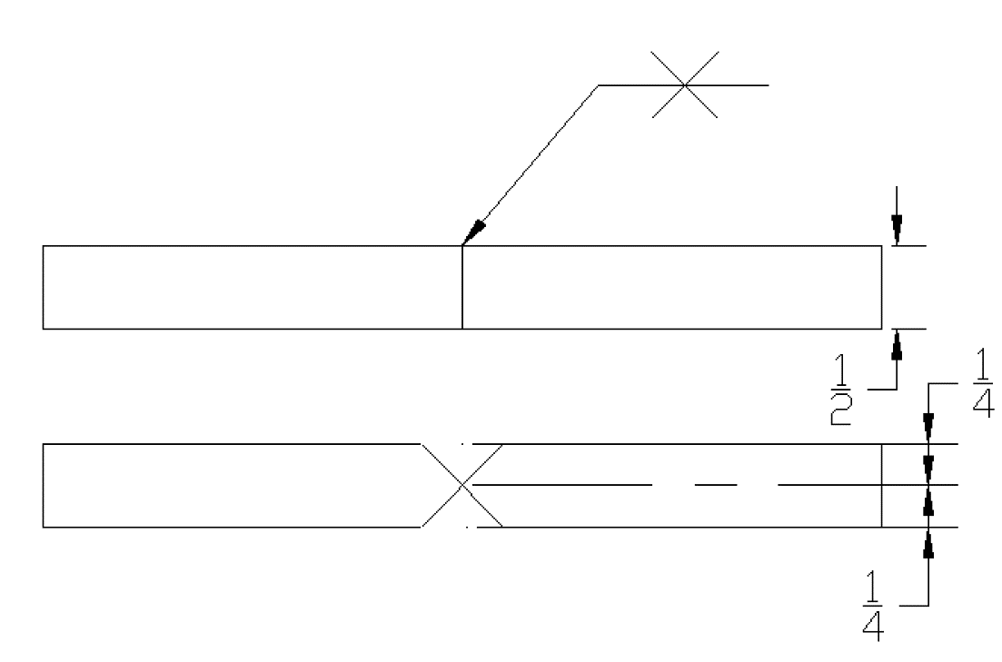
There are also times that a weld is not required to penetrate the depth of the groove. The easiest way to accomplish this would be to place a weld size dimension to the left of the weld symbol that is of smaller size than the material thickness.
There may be a weld applied to both sides in order to get penetration through the groove thickness without preparation of the part. This is going to be limited to smaller thickness of material depending on the process that is used for the welding.
The two flare type grooves including a bevel and a Vee are going to be very common when working with sheet metal and also if there are welds being made to tubing that may have a large radius on the corners. This is fairly common in tubing that is ¼” and above in thickness. If working with sheet metal it is common to make a joint type of this type in order to fuse the parts together. Instead of using filler the material that is making the flare bevel may have a leg of an 1/8” or so and it will make up for the filler.
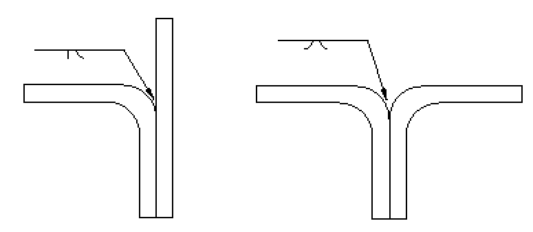
When using either of these symbols it is important to know the difference between the preparation of groove depth as well as the weld size. Similar to a regular bevel or vee the preparation of groove depth is going to be to the left of the weld symbol and also to the left of the weld size which will be shown in parenthesis. Length can be added in a dimension to the right of the weld symbol.
Back, Backing weld, Surfacing weld
A back or backing symbol is the same for both, you must look in the tail for further information to distinguish between them.
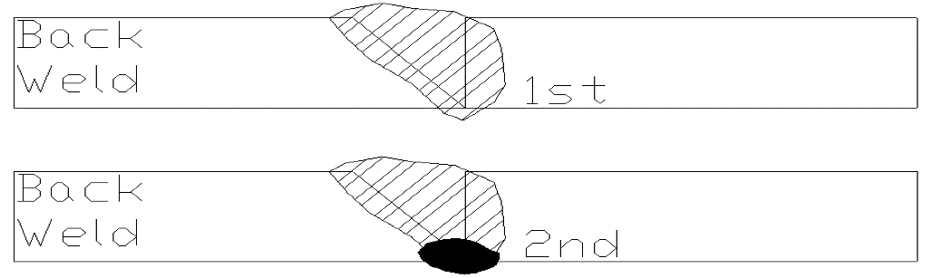
A back weld is when a weld is made in the groove of a joint and followed by a weld applied to the root side. This is most commonly used to insure complete penetration on CJP grooves. The Back weld is usually applied after the root has been ground or gouged out to make sure that the weld is made to sufficient material. When trying to remember the difference between a back and backing weld, you must always go back in order to do a back weld.
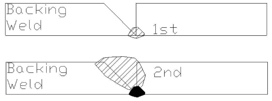
A backing weld is made on the root side of a groove in order to ensure that the weld that is going to be made in the groove does not melt through the backside. This may also help ensure CJP.
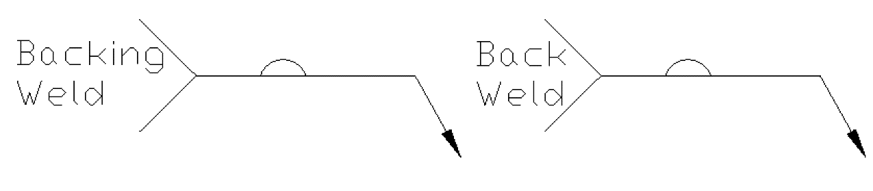
Below is a representation of a backing weld.
Below is a representation of a back weld.
There are times where the tail will be omitted from the drawing and in the tail there will be a note that may say which order the welds are to be made. It may be as simple as “other side weld made first” or may include true terms such as “other side bevel groove welded before back weld on arrow side.”
Surfacing welds
Surfacing welds are made by single or multiple passes to parts for a variety of reasons. These may include buildup of worn material, hard facing a part, or increasing part dimensions. This symbol may be on the arrow side of a joint only. It is important that the arrow points specifically where the surfacing shall be added.
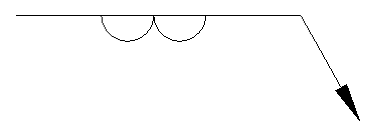
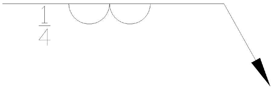
These welds may include a thickness of weld which will be located to the left of the weld symbol and may also show a length to the right of the symbol. With this type of weld it will more than likely have a detail view with dimensions for the welding.
When a surfacing weld may need multiple layers this may be shown in a note on the blueprint or it could also be determined by the reference lines. There are times where there may be more than one reference line which gives it an order of operation. For example if you think of a backing weld this would be listed on the reference line which is closest to the arrow, the groove weld would be placed on the second reference line.
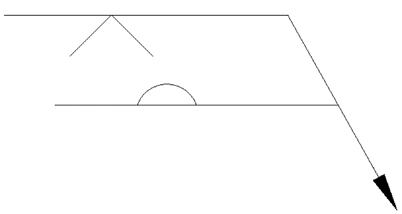
To show this in surfacing welds it may ask for a specific size for the first layer of buildup and then a different size for the second or subsequent layers. If there is a change in direction this may be shown in the tail of a multi reference welding symbol.
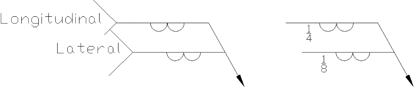
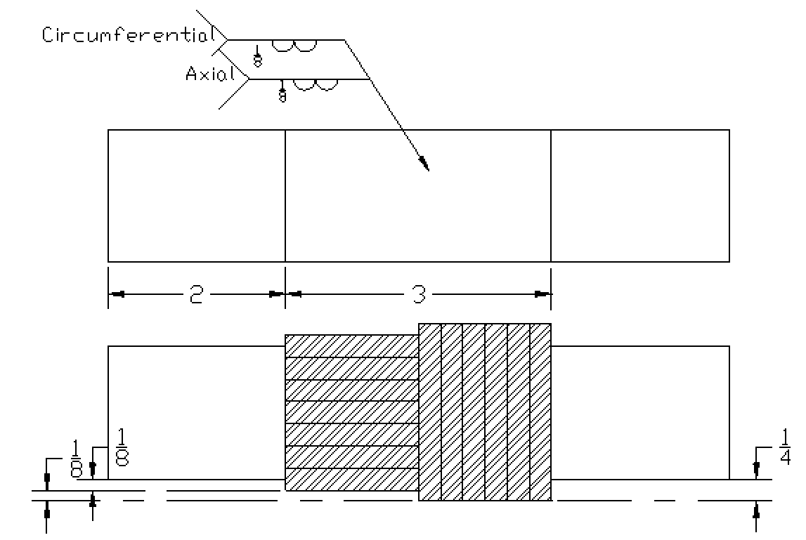
A surfacing weld will run the entire length of the part unless there is a dimension, note, or other designating it is not full. This also plays a part when welding a shaft or other round object. With a round object rather than a longitudinal (long dimension) or lateral (short dimension) of the part you may see axial (the length of the shaft) or circumferential (around the shaft.) When a weld will be done to a shaft or other round part this must be called out or an incorrect procedure may be applied.