
5 Supplementary Welding Symbols
These are symbols that are added onto a weld symbol to give further instruction or knowledge of the final product.
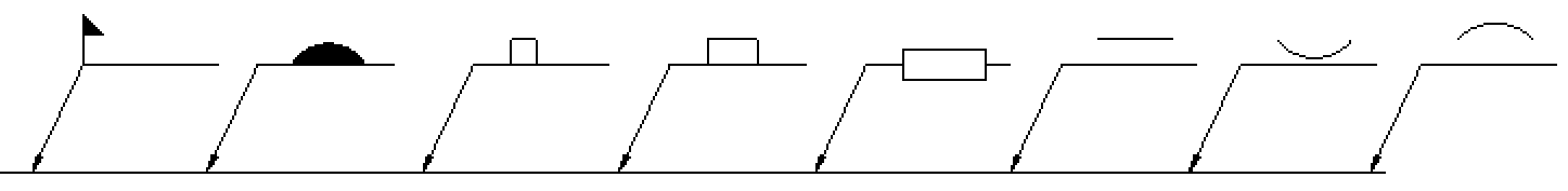
Weld all around
This symbol is simply a circle at the junction of the arrow and the reference line. This indicates that on a part that a weld could be completed around an entire joint. A common place you could see this is the junction of a square or round tube and a plate.
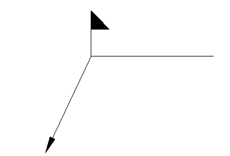
Field Weld
The symbol is a flag that will be at the junction of the arrow and reference line. This indicates that the part while may be assembled in a shop setting, its final welding procedures will be completed in the field during installation. The flag itself should point in the direction of the tail (end of reference line.) It can also be placed above or below the reference line for an other or arrow side specification.
Melt Through
Melt through is most commonly associated with a groove weld. This is indicating you are achieving 100% penetration with a root reinforcement. This symbol can also be seen when sheet metal is being welded and there is an implied melt through in seams and joints.
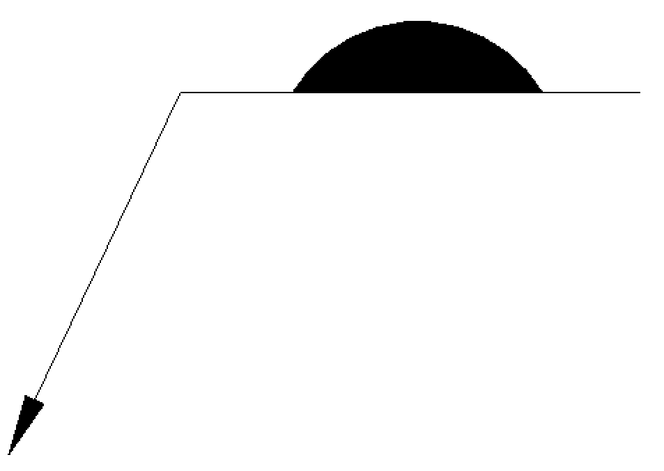
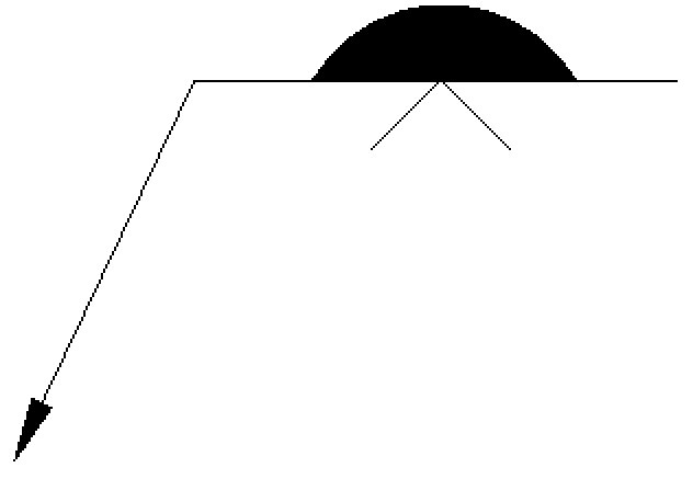
Melt through may include a finishing contour as well as finishing method as parts are often cleaned up before they are sent to be painted, powder coated, or put into service.
Consumable Insert
A consumable insert symbol is used when an insert is used within a welded joint that becomes part of the weld. These are commonly specified in shape, size, and material. The symbol is placed on the opposite side of the groove weld symbol. The consumable insert class must be placed in the tail of the welding symbol. This class is defined by the American Welding Society.
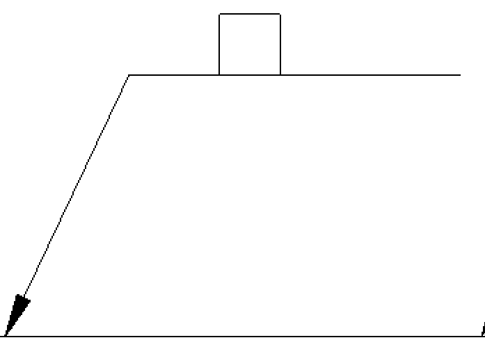
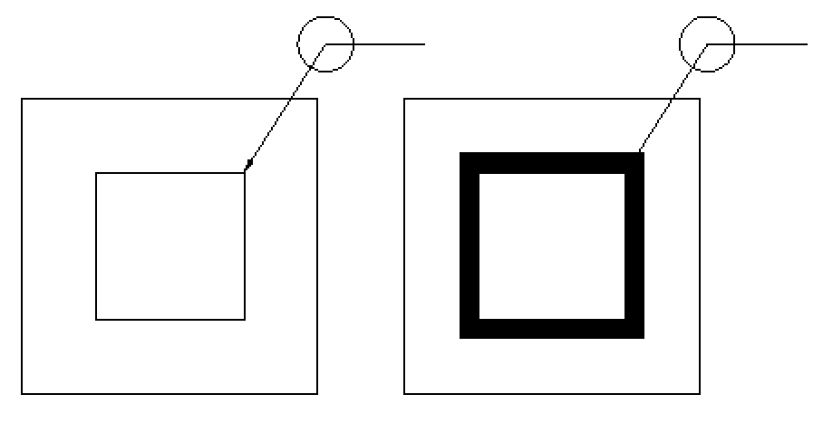
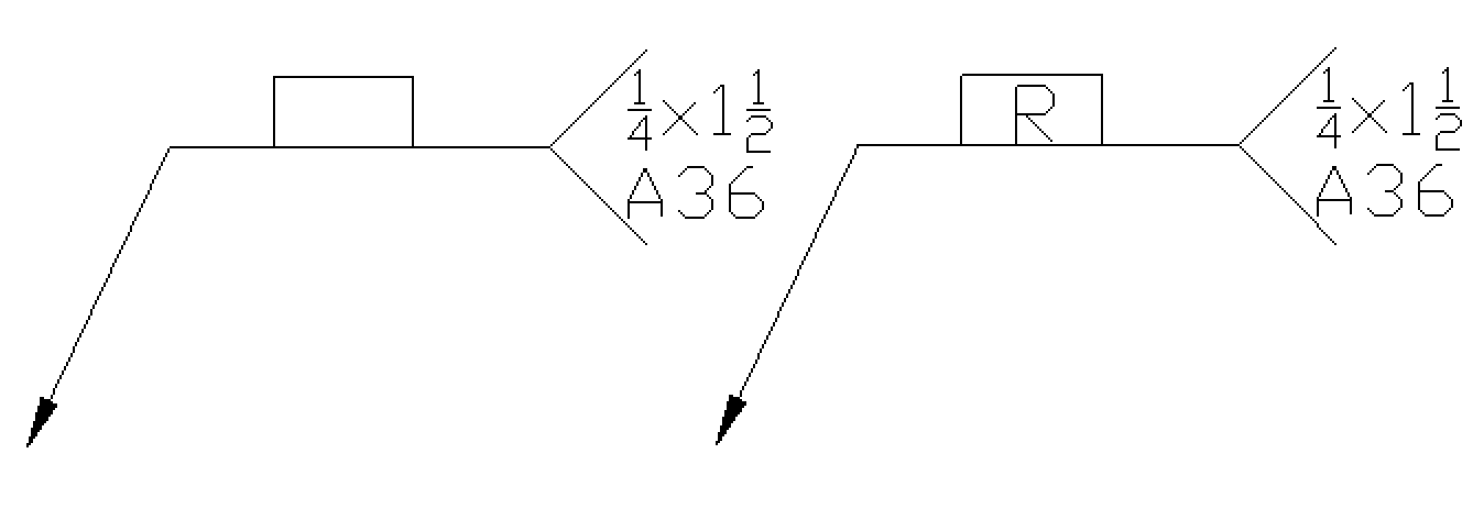
Backing
A backing strip is specified by placing a rectangle on the opposite side of the reference line from the groove weld symbol. If the backing must be removed after the welding operation has been finished, the letter R must be placed inside of the backing symbol. Material to be used as well as the dimensions must be placed in the tail of the symbol or somewhere on the drawing.
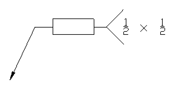
Spacer
A spacer may be used on a double groove weld. In this case both the top and bottom are prepped and a spacer is added to the middle of the groove. The symbol is a rectangle the breaks the reference line. A note on the print or in the tail can specify material and dimensions.
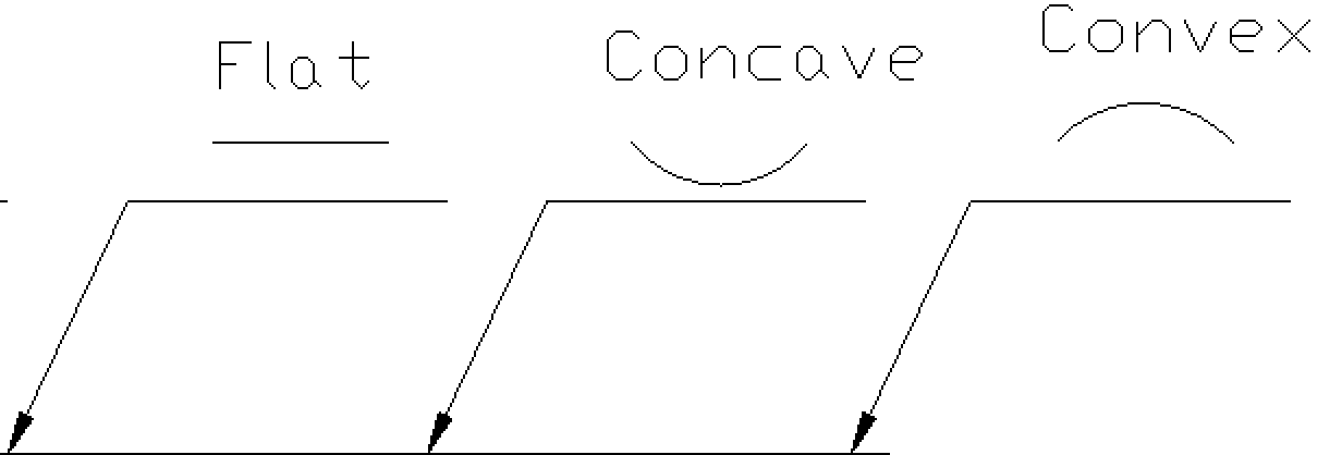
Weld contour
There are 3 symbols used for specifying the contour finish of a weld. This is the final appearance of a weld as it goes into service. These are commonly associated with fillet welds but sometimes will present themselves with groove welds. If a “flat” symbol is used with a groove weld it will then be called a flush contour rather than flat.
Contour symbols may also include yet another element which will show to the right of the fillet weld symbol above the contour. These are letter designations which will be for finishing methods.
C- Chipping
G- Grinding
H- Hammering
M- Machining
P- Planishing
R- Rolling
U- Unspecified
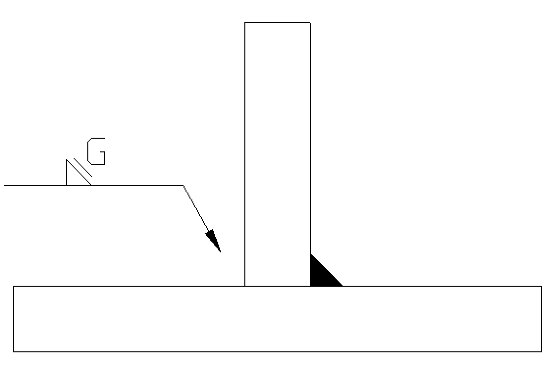
Shown is a fillet weld to be applied to the other side with a flat contour by grinding.
