13 Pipe Drawings
Pipe drawings differ from common blueprints one would see in the construction or welding field. The drawings we often see in these fields would be orthographic views which may include top, front, right side, left side, bottom, and back views depending on what is needed to convey information. Pipe drawings are presented in an Isometric view (ISO.) This view is drawn in order to show a pictorial view of what is needed. Commonly these are drawn at a 30 degree angle from the horizontal plane. This can cause some distortion in dimensions so it is imperative that the correct dimensions are shown.
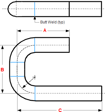
The image below shows a orthographic view of a butt welded pipe with three sizes (A, B, C).
- The A size is measured from the front to the center line of the elbow / pipe.
- The B size is measured from centerline to centerline.
- The C size is like the A size, measured from the front to the center line of the elbow / pipe.
ORTHOGRAPHIC VIEW
(DOUBLE LINE PRESENTATION) ISOMETRIC VIEW
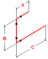
Isometric, Plan and Elevation Presentations of a Piping System
The image below show the presentation used in drafting. The isometric view clearly show the piping arrangement, but the plan view fails to show the bypass loop and valve, and the supplementary elevation view is needed.
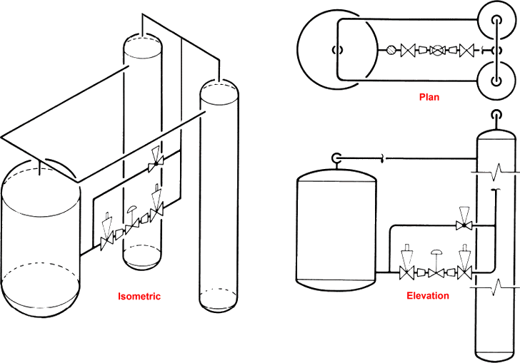
Isometric views in more than one plane
Below are some examples of isometric drawings. The auxiliary lines in the shape of a cube, ensure better visualization of the pipeline routing.
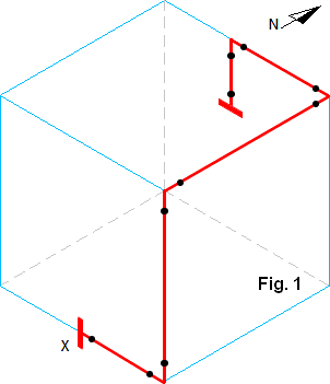
Figure 1 shows a pipeline which runs through three planes. The pipe line begins and ends with a flange.
Routing starting point X
- pipe runs to the east
- pipe runs up
- pipe runs to the north
- pipe runs to the west
- pipe runs down
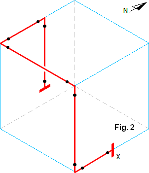
Figure 2 is almost identical to the drawing above. A different perspective is shown, and the pipe that comes from above is longer.
Because this pipe in isometric view, runs behind the other pipe, this must be indicated by a break in the line.
Routing starting point X
- pipe runs to the south
- pipe runs up
- pipe runs to the west
- pipe runs to the north
- pipe runs down
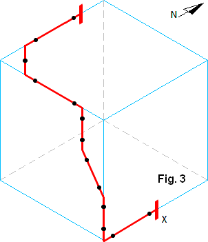
Figure 3 shows a pipe that runs through three planes and in two planes it make a bow.
Routing starting point X
- pipe runs to the south
- pipe runs up
- pipe runs up and to the west
- pipe runs up
- pipe runs to the west
- pipe runs to the north-west
- pipe runs to the north
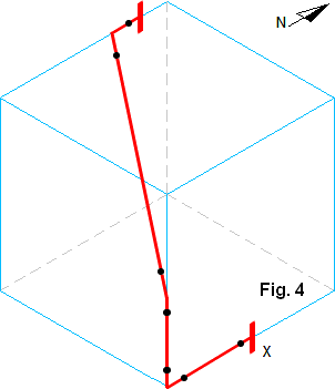
Figure 4 shows a pipe that runs through three planes, from one plane to a opposite plane.
Routing starting point X
- pipe runs to the south
- pipe runs up
- pipe runs up and to the north-west
- pipe runs to the north

