
58 Unit 6 Practice and Assessment
Outcome 1
1) Consider the following items:
- Pliers
- Tweezers
- Shovel
(a) For each case, draw a stick figure of the tool and label the fulcrum, effort, load, effort arm and load arm.
(b) State the class of lever for each item above.
2) For each item in the list in Exercise 1), state whether the tool is providing mechanical advantage or increasing range of motion. Explain how you know.
Outcome 2
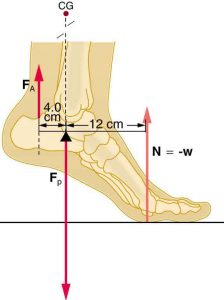
3) When a person raises their heels off the ground, the foot acts like a lever.
(a) Typically we consider the foot as a second class lever, but if we treat the ankle bone as the fulcrum, the tension in the calf muscle as the effort, and the normal force from the floor as the resistance, what class of lever is this system?
(b) Calculate the mechanical advantage of this system.
(c) Calculate the tension applied by the calf muscles ( ) to lift a person with weight of 637 N.
(d)Calculate the force in the ankle joint between the foot and the lower leg bones ( ). [Hint: Both the normal force from the floor and the calf tension point upward. In order for the foot to be in static equilibrium, the force of the lower leg pushing down on the foot must cancel out both of those upward forces.]
(e) Convert your previous two answers (calf tension and force on ankle) to pounds.
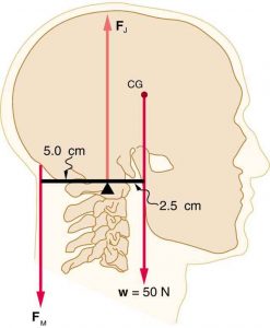
4) The head and neck are also a lever system.
(a) State the class of this lever system.
(b) Calculate the mechanical advantage of this system.
(c) Calculate the force of tension in the neck muscles ( ) to hold the head in the position shown in the diagram.
(d) Calculate the force on the head-neck joint ( ).
).
(e) Convert your previous two answers to pounds.
5) The structure in the following image remains at rest. What do you know about the force and net torque on the structure?
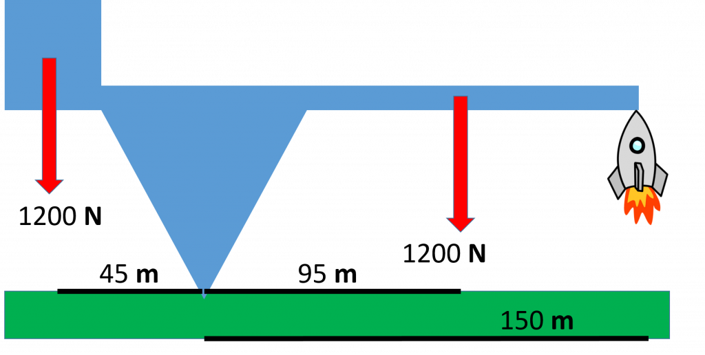
6) An engineer performing an inspection on the structure from the previous exercise and measures 45 m from beneath the center of gravity of the block to the point where the structure contacts the ground. The block weighs 1200 N. She then measures the distance to the beneath the center of gravity of the arm to be 95 m. The arm weighs 1200 N as well. Finally she measures the distance to beneath the rocket to be 150 m from the contact point. She then calculates the force being provided by the rocket.
(a) What value does the engineer get when calculating the force provided by the rocket? [Hint: Pretend the rocket isn’t there and calculate the net torque. Then find the force supplied by the rocket to balance out that net torque.]
(b) The engineer then calculates the normal force on the structure from the ground, what value does she get?
Outcome 3
7) Label the following features in the stress-strain curve of a hypothetical material seen below:
- Toe region
- Elastic region
- Yield point
- Plastic Region
- Ultimate Strength
- Rupture Point
- Failure Region
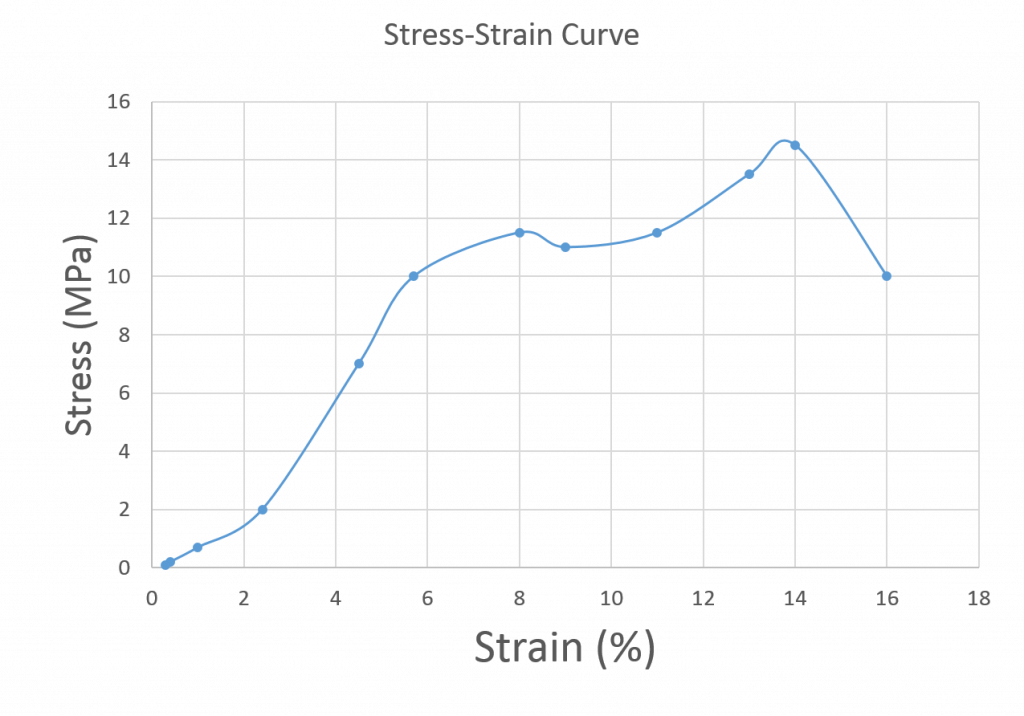
8) Use the data in the previous graph to determine the elastic modulus of the hypothetical material. Be sure to convert the strain from % stretch back to fractional stretch before doing your calculations.
Outcome 4
9) A person with a weight of 715 N hangs from a climbing rope 9.2 mm in diameter.
a) What is the cross-sectional area of the rope in m2?
b) What is the stress applied to the rope?
10) A particular 60 m climbing rope stretches by 0.15 m when a 715 N person hangs from it.
a) What is the strain in the rope?
b) What is the strain in the rope as a percentage?
11) Answer the following questions regarding the material used to create the created the stress-strain graph above.
a) How much force could be applied to a 2 m x 2 m x 10 m long block of this material before reaching the ultimate strength?
b) When operating in the elastic region, how much additional stress would be required to cause an additional strain of 0.01?
c) What force would cause that amount of stress you found in part b on the 2 m x 2 m block?
d) What actual length would the 10 m long material stretch when put under the strain of 0.01?
e) What is the effective spring constant of this 2 m x 2 m x 10 m long block of this material?
- OpenStax, College Physics. OpenStax CNX. Aug 3, 2018 http://cnx.org/contents/031da8d3-b525-429c-80cf-6c8ed997733a@11.42 ↵
- OpenStax, College Physics. OpenStax CNX. Aug 3, 2018 http://cnx.org/contents/031da8d3-b525-429c-80cf-6c8ed997733a@11.42 ↵
the point on which a lever rests or is supported and on which it pivots
referring to a lever system, the force applied in order to hold or lift the load
a weight or other force being moved or held by a structure such as a lever
in a lever, the distance from the line of action of the effort to the fulcrum or pivot
shortest distance from the line of action of the resistance to the fulcrum
ratio of the output and input forces of a machine
distance or angle traversed by a body part
levers with the resistance (load) in-between the effort and the fulcrum
the force that is provided by an object in response to being pulled tight by forces acting from opposite ends, typically in reference to a rope, cable or wire
the outward force supplied by an object in response to being compressed from opposite directions, typically in reference to solid objects.
the force working against the rotation of a lever that would be caused by the effort
measures of resistance to being deformed elastically under applied stress, defined as the slope of the stress vs. strain curve in the elastic region
The cross-sectional area is the area of a two-dimensional shape that is obtained when a three-dimensional object - such as a cylinder - is sliced perpendicular to some specified axis at a point. For example, the cross-section of a cylinder - when sliced parallel to its base - is a circle
a physical quantity that expresses the internal forces that neighboring particles of material exert on each other
the measure of the relative deformation of the material
the maximum stress a material can withstand
the range of values for stress and strain values over which a material returns to its original shape after deformation
measure of the stiffness of a spring, defined as the slope of the force vs. displacement curve for a spring
